TP-6727 10/1128 Section 3 Installation Instructions
1
GM78230
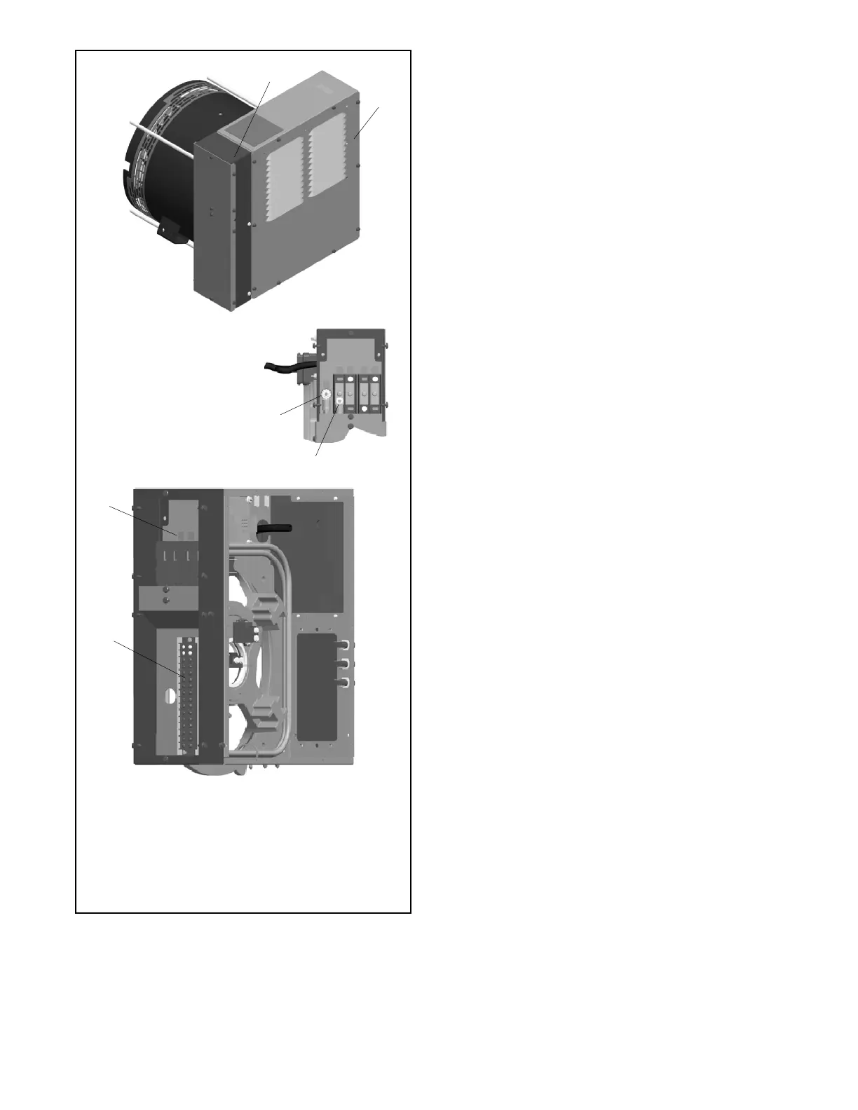
1. Customer connection box with cover plates
2. End panel. Do not remove.
3. AC connection terminal block TB2 (see detail)
4. Ground terminal
5. L0 terminal
6. DC connection terminal block TB1 (cover removed)
Note: See the wiring diagram for connection details.
GM78207
6
3
2
5
4
GND and L0 Connection Detail
Figure 3-2 Customer Connection Box
3.5 Generator Set Electrical
Connections
Note: Have a licensed electrician make the following
electrical connections. All connections must
comply with state and local codes.
Size the wire according to the length of run and 115% of
the circuit current (amperage) as directed by the
National Electrical Code r (NEC) in ANSI/NFPA 70.
Refer to the diagrams in the wiring diagram manual
provided with the generator set.
See Figure 3-1 or Figure 3-2. On units equipped with
the customer connection box shown in Figure 3-2, make
all AC and DC customer connections inside the
customer connection box. Do not remove the end panel
or make connections inside the junction box.
Load Lead and Engine Start Connections
1. Install a 120 VAC receptacle for the generator set
battery charger and block heater, if equipped.
Supply power to the receptacle through a circuit
that is powered at all times, by the utility and by the
generator set during utility power outages.
2. Some codes require the use of a disconnect switch.
Check the code requirements for your location and
install a disconnect switch, if required.
3. Use separate conduit for the power cables and the
low voltage engine start leads. Local codes and the
length of run as well as the transfer switch wire size
requirements will determine the wire size needed
for the AC leads. Route the load leads into the
junction box through the access opening in the
back of the box. On units with the customer
connection box, make openings in the top or side of
the box and route the leads to TB1 and TB2 through
separate conduit.
4. Connect the load leads from the line circuit breaker
in the generator set junction box to the transfer
switch emergency power connection points. See
Figure 3-1 and refer to the transfer switch
Installation Manual for ATS connection
instructions.
 Loading...


