TP-6137 5/03 55Section 9 Generator Troubleshooting
9.6 Stator Test
Stator Insulation, Continuity, and Winding
Resistance Test
1. Disconnect the generator set’s AC output leads
from the control box.
Note: Refer to the Wiring Diagrams in Section 11 and
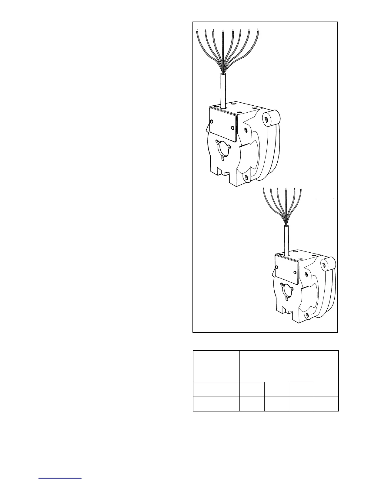
Figure 9-8 for output lead coding.
2. Check the windings insulation resistance to
ground.
Note: Remember that while checking, isolate each part
from the others.
3. Use a Megger set at 500 volts DC. If winding
resistance values to ground is ≥ 1 MOhm, consider
the insulation good. If the resistance is lower than
1 MOhm, replace the stator.
4. Using an ohmmeter, test for an open circuit in the
stator winding.
Note: If an accurate ohmmeter is unavailable, check
the circuit’s continuity using a 12 volt DC battery
and a suitable lamp.
5. Replace the stator if it has an open or short circuit in
the windings.
Note: Some generators have ground connections to
the frame (to ground), check the Wiring Diagrams
in Section 11.
6. Using a Kelvin bridge or an accurate
microhmmeter, test the resistance of each stator
windings and compare the resistances obtained.
See Figure 9-9. All windings of equal output
voltage should indicate about the same resistance.
An unusually low reading indicates a short circuit
while a high reading indicates an open circuit.
7. If an open or short circuit exists, replace the stator.
1 2 3 4 10 11 C1 C2
1 2 10 11C1 C2
60 Hz
50 Hz
Figure 9-8 Stator Windings
Resistance in Ohms at 20_ C(68_ F)
Stator Leads
Model
1--2
1--2
3--4
C1--C2 10--11
4EOZ (60 Hz)
0.96
±10%
2.32
±10%
0.068
±10%
3.5EFOZ (50 Hz)
1.23
±10%
2.87
±10%
0.091
±10%
Figure 9-9 Resistance Values
 Loading...

