TP-6390 1/06 13Section 1 Service Views
Section 1 Service Views
15
2
20
28 27
22
25
29
4
30
10 11
12
18
17
13
9
21
26
87
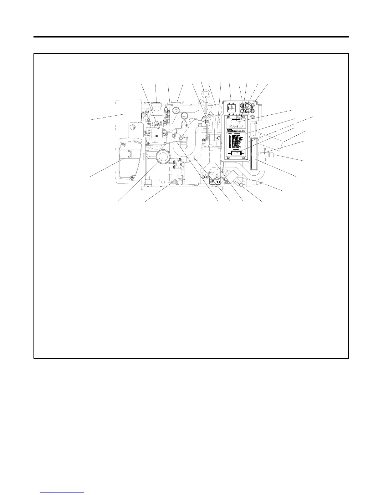
SERVICE VIEW
1 3
19
1. Spark plug (also one located on the nonservice side)
2. Oil fill
3. Overflow tube
4. Pressure cap (coolant fill location after draining coolant)
5. Seawater pressure switch (appears as auxiliary fault on ADC)
6. Lifting eye
7. Heat exchanger
8. Anticorrosion zinc anode
9. AC circuit breaker
10. AC load lead connector (nonservice side)
11. Nameplate (top)
12. Customer interface connection (nonservice side)
13. Fuses (F1, F2, F3, F4, F5, F6, and F7)
(see Section 2.7.2)
14. Runtime hour display
15. Advanced Digital Control (ADC 2100)
16. CO sensor module
17. Generator set master switch
18. Catalyst assembly, water outlet/exhaust outlet (nonservice
side)
19. Seawater drain (remove plate for service)
20. Seawater pump (water inlet)
21. Cooling air inlet
22. Fuel filter/fuel inlet
23. Fuel pump
24. Fuel pump/cooler
25. Oil check
26. Coolant drain (remove hose clamp to drain coolant)
27. Oil drain valve
28. Lube oil filter
29. Coolant overflow bottle (daily coolant check/fill location)
30. Air intake silencer/backfire flame arrestor
Note: Consult installation drawings in Spec Sheet or Installation
Manual for fuel- and battery-connection points.
Note: Consult distributor/dealer or Service Manual for items
not shown.
24
5
14
23
6
ADV7025A-A
16
Figure 1-1 Service Views
 Loading...


