TP-6390 1/0616 Section 2 Operation
2.3 Angular Operation
See Figure 2-1 for angular operation limits for units
covered in this manual.
Continuous
Intermittent—
3 minutes or less
25_ 30_
Maximum value for all directions
Figure 2-1 Angular Operation
2.4 Operation in European Union
Member Countries
This generator set is specifically intended and approved
for operation below the deck in the engine compartment.
Operation above the deck and/or outdoors would
constitute a violation of European Union Directive
2000/14/EC noise emission standard.
2.5 Load Profile
Whenever operating the generator set, Kohler Co.
recommends maintaining the minimum load profile
indicated in Figure 2-2. Maintaining the load profile
prevents corrosion formation on internal engine
components when they’re exposed to the breakdown of
exhaust gases.
Minimum
Load Requirement
Ideal
Load Requirement
30% load 70% load or more
Figure 2-2 Load Profile
The operator should perform all of the prestart checks.
Start the generator set according to the starting
procedure in the controller section of this manual. While
the generator set is operating, listen for a
smooth-running engine and visually inspect the
generator set for fluid or exhaust leaks.
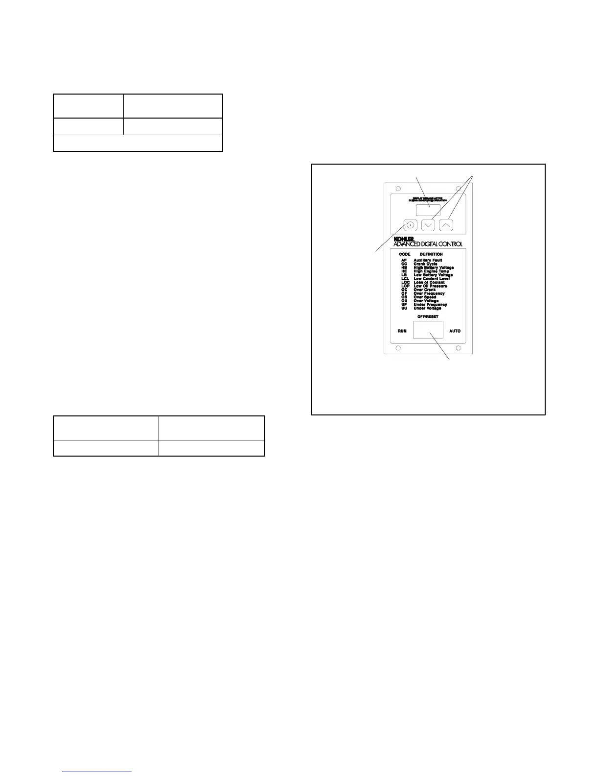
2.6 Advanced Digital Control
Operation
Figure 2-3 illustrates the user interface on the Advanced
Digital Control (ADC 2100).
Note: Have setup and adjustments of the ADC 2100
performed only by an authorized Kohler
distributor/dealer. The setup and adjustments
are password protected.
GM28707A-C
1. LED display
2. Up and down arrow buttons (use for setup and adjustment
only)
3. Generator set master switch
4. Select button (use for setup and adjustment only)
1
4
3
2
Figure 2-3 ADC 2100 Control
2.6.1 Controls and Indicators
Figure 2-4 describes the controls and indicators located
on the controller. The LED display indicates generator set
status as shown in Figure 2-4. The display is active when
the master switch is in the RUN or AUTO position and
remains active until the generator set master switch is
moved to the OFF/RESET position or the power to the
controller is removed.
The buttons on the controller keypad are used only for
system configuration and adjustment. The controller is
factory-set and should not require configuration or
adjustment under normal operating conditions. If the
generator set is reconnected to a different voltage
and/or frequency, refer to an authorized Kohler
distributor/dealer for system configuration and
adjustment instructions.
 Loading...


