TP-6390 1/0622 Section 2 Operation
2.6.6 Resetting the Controller after a
Fault Shutdown
Always identify and correct the cause of a fault
shutdown before resetting the controller. Use the
following procedure to reset the generator set controller
after a fault shutdown.
1. Move the generator set master switch to the
OFF/RESET position.
2. Disconnect the generator set from the load using
the line circuit breaker. See the safety precautions
at the beginning of this manual before proceeding.
3. Identify and correct the cause of the fault
shutdown. See the safety precautions at the
beginning of this manual before proceeding. Refer
to Section 4, Troubleshooting.
4. Start the generator set by moving the generator set
master switch to RUN. Test operate the generator
set to verify that the cause of the shutdown has
been corrected.
5. Shut the generator off by moving the generator set
master switch to the OFF/RESET position.
6. Reconnect the generator set to the load using the
line circuit breaker.
7. Move the generator set master switch to the AUTO
position for startup by remote transfer switch,
remote start/stop switch, or remote digital gauge.
Opening and closing the remote start/stop contact
also resets the controller.
2.6.7 Continuous Power Mode if
Equipped with a Remote Gauge
The controller is powered by the generator set engine
starting battery.
Remote communications require an active
(powered-up) controller. Be advised that the ADC
consumes 250 mA when the master switch is in the
AUTO position. If you do not plan to use your generator
set for a long period of time, Kohler recommends
moving the master switch to the OFF/RESET position
(complete power down—0 mA draw).
A remote start signal (from a transfer switch or a remote
start/stop switch connected to P21 connector, leads 3
and 4) or moving the generator set master switch to the
RUN position turns the controller back on.
2.7 Circuit Protection
If the generator set circuit breaker trips or the fuses blow
repeatedly, see Section 4 for possible causes.
2.7.1 Line Circuit Breaker
A line circuit breaker interrupts the generator output in
the event of a fault in the wiring between the generator
and the load. The line circuit breaker location is shown
in Section 1. If the circuit breaker trips, reduce the load
and switch the breaker back to the ON position.
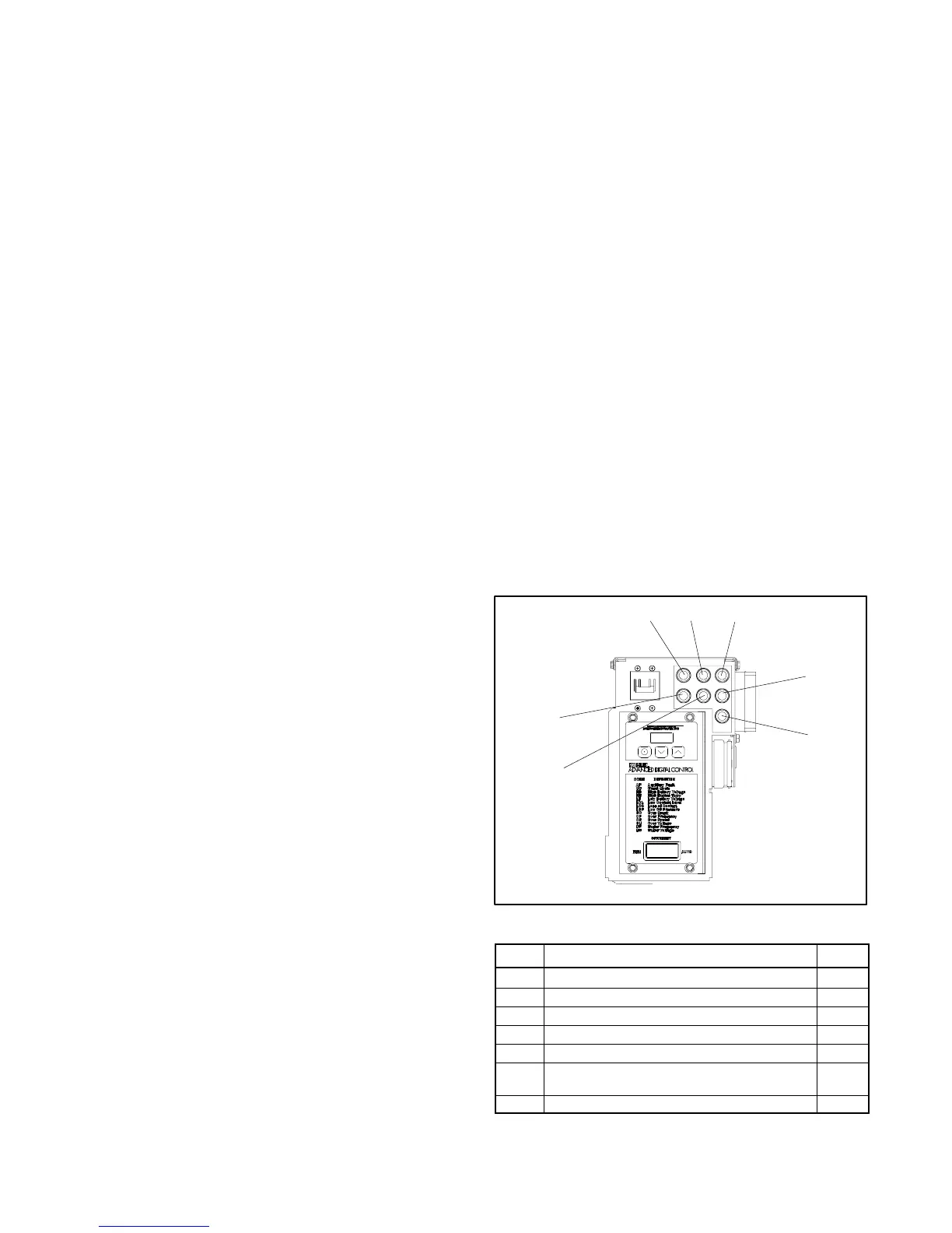
2.7.2 Fuses
The junction box contains seven fuses. See Section 1
and Figure 2-9 for the fuse location. Always identify and
correct the cause of a blown fuse before restarting the
generator set. Refer to section 4 for conditions that may
indicate a blown fuse. Obtain service from an
authorized distributor/dealer.
ADV7025A-A
F1 F2 F3
F4
F5
F6
F7
Figure 2-9 Fuse Identification
Label Fuse Amps
F1 Auxiliary Winding 10
F2 Controller 10
F3 Customer Connection 10
F4 Coils/Injectors 15
F5 ECM, O
2
Sensor, and Fuel Pumps 15
F6 Voltage Regulator and Battery Charging
Alternator
15
F7 Starter Motor and Crank Solenoid 20
Figure 2-10 Fuses
 Loading...


