TT-1617 12/13 5
6. Install the relay in the junction box.
6.1 Use a 5/16 in. socket, 1/4 in. drive to remove the
junction box cover.
6.2 Place a rag inside the junction box to catch any
filings.
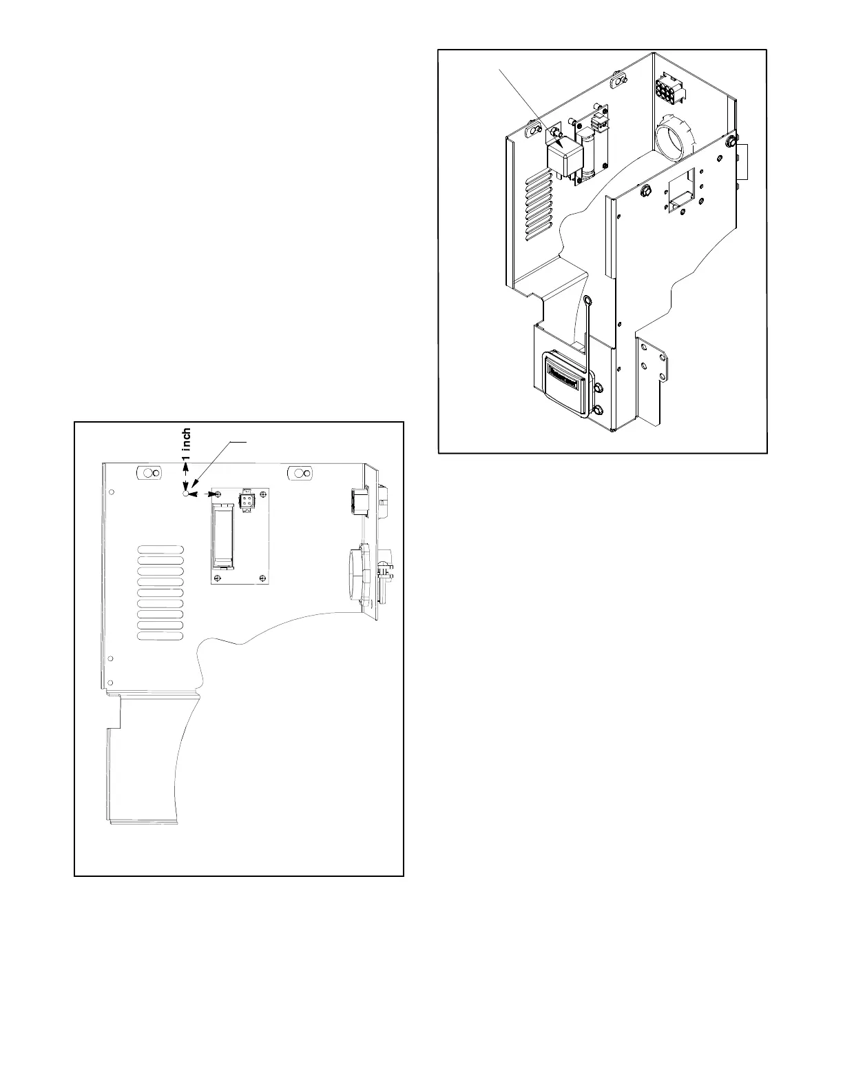
6.3 Drill a 3/16 in. hole at the location shown in
Figure 11.
6.4 Remove the rag and any drill filings from inside of
the junction box.
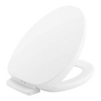
6.5 Mount the relay (GM49746) at the location shown
in Figure 12 using a screw (X-50-1) and nut
(X-70-3).
6.6 Connect the relay-connector end of the new wiring
harness (GM90471) to the new relay (GM49746).
6.7 Use a 5/16 in socket, 1/4 in. drive to reinstall the
junction box cover.
1
GM40265-D
1. 3/16 in. hole
(1 in. down from top edge and 1 in. over from pem stud)
1
inch
Figure 11 Hole Location for Relay (Inside Junction
Box)
1
GM40265-D
1. Relay (GM49746), screw (X-50-1), and nut (X-70-3)
Figure 12 Relay Location (Inside Junction Box)
 Loading...