6 TT-1617 12/13
7. Install the flow switch.
7.1 For Units Without a Siphon Break:
Note: Proceed to Section 7.2 for units with a
siphon break.
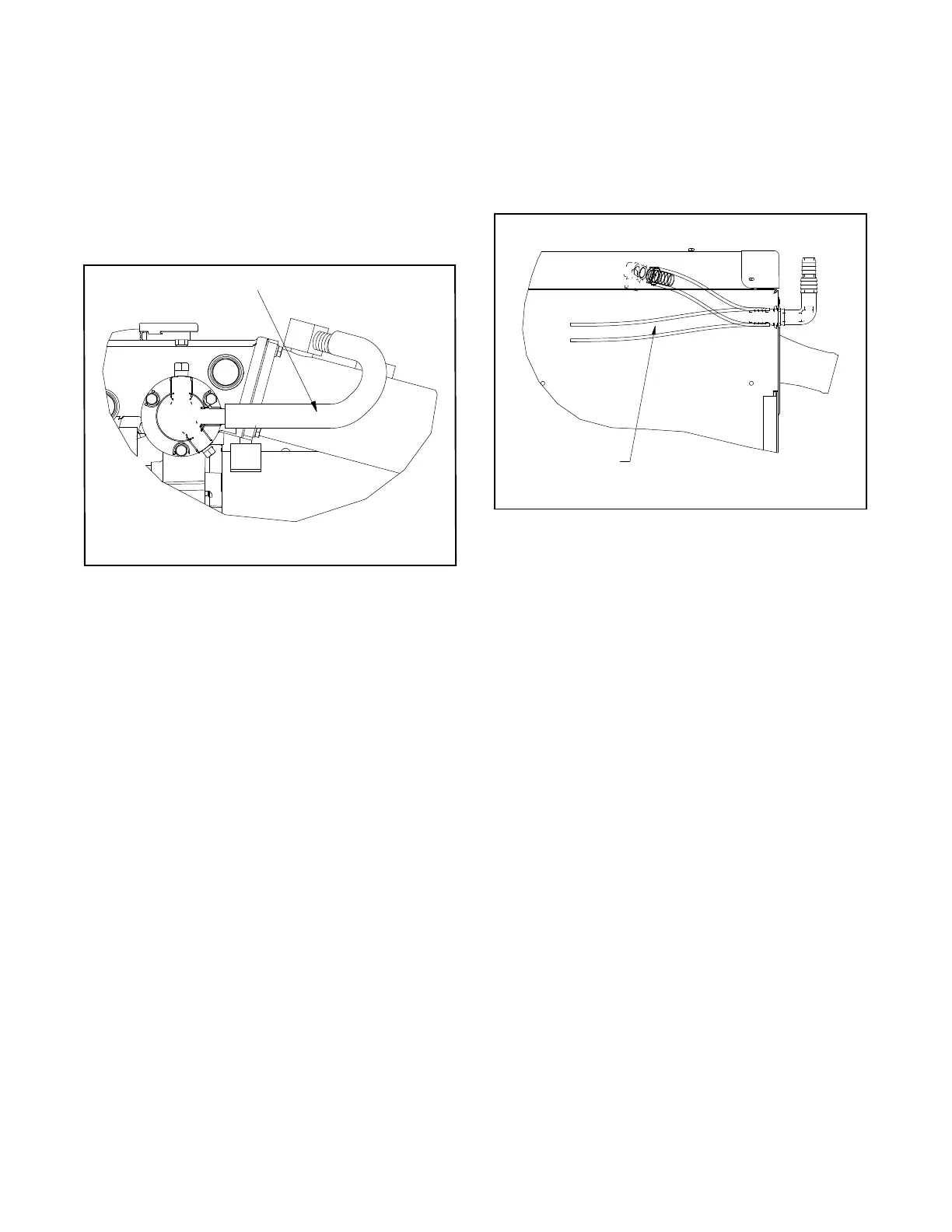
7.1.1 Remove the molded hose located
between the heat exchanger end cap and
catalyst. See Figure 13. Save the molded
hose for re-use.
1
GM58158-L
1. Remove this hose.
Figure 13 Hose Location (Units Without Siphon
Break)
7.1.2 Install a new hose (X-312-42), flow switch
(GM90436), and hose fittings (GM90472
qty. 2) as shown in Figure 15.
Note: Use Teflon tape on the threads of
the flow switch fittings. Wrap the
tape around at least 3 times.
Note: Avoid any kinks in hoses that
connect to the flow switch.
7.1.3 Reuse the molded hose (removed in
Step 7.1.1) but spin the hose 180_ from its
original position. See Figure 15, item 1.
7.1.4 Secure the hoses using hose clamps
(X-426-12 qty. 2) and existing hose
clamps.
7.1.5 Connect the flow switch connector to the
new wiring harness connector that was
routed to the nonservice side in Step 5.2.
7.2 For Units With a Siphon Break:
7.2.1 Remove the hose located between the
heat exchanger end cap and the hose
connector. See Figure 14.
7.2.2 Cut this hose into a 4-inch piece and a
5-inch piece.
1
GM60007-A
1. Remove this hose.
Figure 14 Hose Location (Units With Siphon Break)
7.2.3 Reuse the hose (cut to 4 inches in
Step 7.2.2) as shown in Figure 15, item 4.
Install the flow switch (GM90436), and
hose fittings (GM90472 qty. 2) as shown in
Figure 15.
Note: Units equipped with a siphon break
will not use the new hose X-312-42
supplied in the kit.
Note: Use Teflon tape on the threads of
the flow switch fittings. Wrap the
tape around at least 3 times.
Note: Avoid any kinks in hoses that
connect to the flow switch.
7.2.4 Reuse the hose cut to 5 inches in
Step 7.2.2) as shown in Figure 15, item 2.
7.2.5 Secure the hoses using hose clamps
(X-426-12 qty. 2) and existing hose
clamps.
7.2.6 Connect the flow switch connector to the
new wiring harness connector that was
routed to the nonservice side in Step 5.2.
 Loading...