TP-6196 10/09 67Section 5 ADC-RES and DC-RET Controller
5.8 Optional Relay Board
The generator set may be equipped with an optional
relay board, which contains the K1 common fault relay
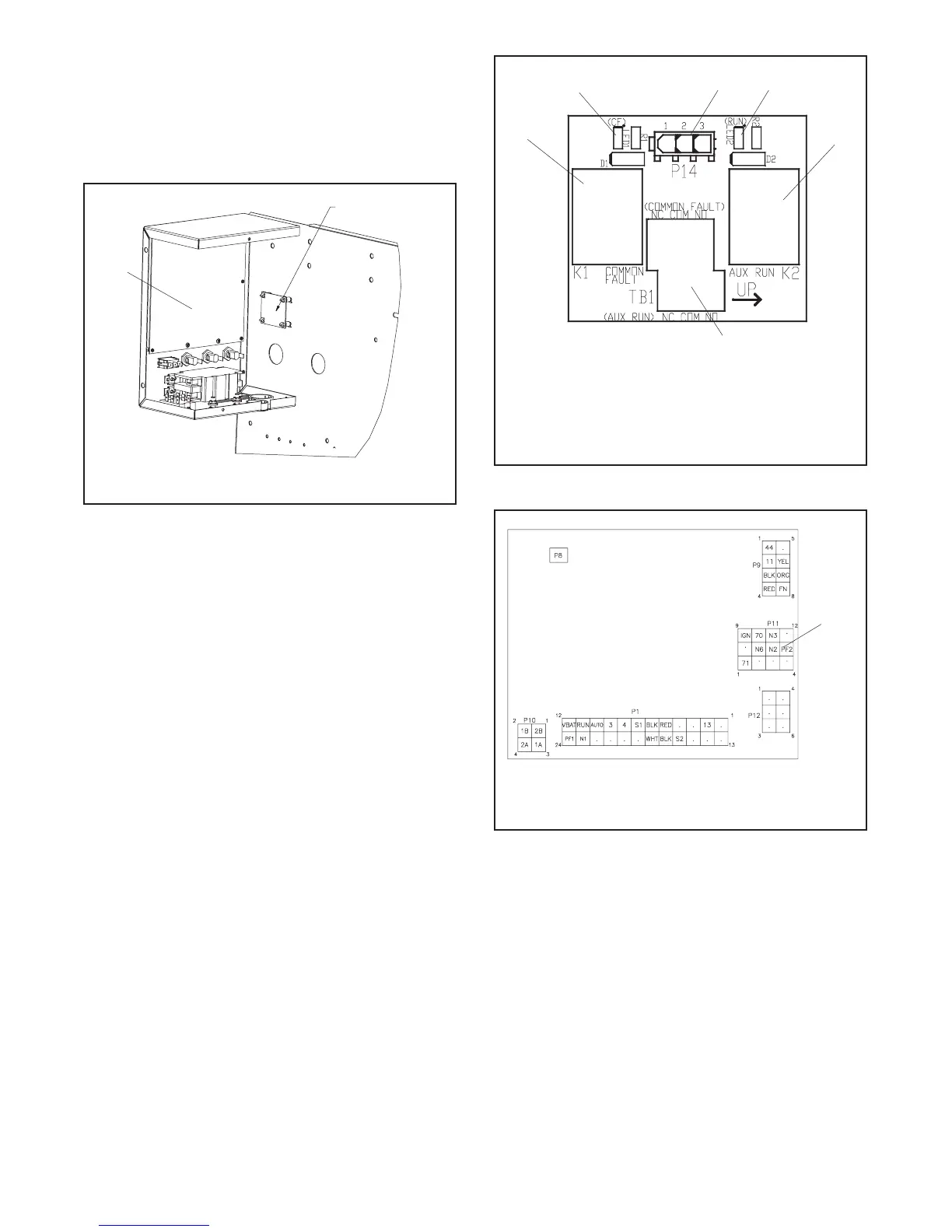
and K4 auxiliary run relay. See Figure 5-17 for the relay
board location inside the controller junction box.
GM53102
1
2
1. Relay board
2. Controller circuit board location
Figure 5-17 Relay Board Location
(inside controller junction box)
5.8.1 Relay Board Troubleshooting
First check for loose connections. Check the relay
board harness connections to the relay board, control
board, and engine harness. See Figure 5-18,
Figure 5-19, and Figure 5-20.
Check for loose customer connections to terminal strip
TB1 on the relay board. See Figure 5-18 and
Figure 5-21.
Check the harness and wiring for open circuits or shorts.
Replace the harness or customer wiring as necessary.
Check that the ratings of the customer’s connected
equipment do not exceed the relay contact
specifications shown in Figure 5-22.
An LED is associated with each relay. See Figure 5-18.
The LED indicates power to the corresponding relay. If
the LED is illuminated but the relay is not activated, the
relay is faulty. The individual relays are not replaceable.
If one or more relays are faulty, replace the entire RIB.
See Section 5.8.2, Relay Board Replacement
Procedure.
5
1. K1 common fault (CF) relay
2. LED1 (for K1 CF relay)
3. Connect P14 from RIB harness GM52639 to P14 on the
relay board
4. LED2 (for K2 aux. run relay)
5. K2 auxiliary run relay
6. Connect customer equipment to TB1, 14 AWG max.
2
1
6
3
GM51403
4
Figure 5-18 Optional Relay Board
from GM52541
1. P11, Relay board harness connection to the controller board.
1
Figure 5-19 Relay Board Harness Connection to
Controller Circuit Board
 Loading...