TP-6196 10/0998 Section 6 Component Testing and Adjustment
6.13 Fuses
Three fuses are located on the junction box next to the
controller display/keypad. (Early models may have the
fuses located in the wiring harness.) See Figure 6-41.
Another 10-amp fuse protects the battery charger.
Fuse Label Part Number
Auxiliary Winding, 20 amps F1 292937
Relay Interface Board, 10 amps F2 223316
Controller, 10 amps F3 223316
Battery Charger, 10 amps — 223316
Figure 6-41 Fuses
Always identify and correct the cause of a blown fuse
before restarting the generator set. Refer to Section 3,
Troubleshooting, for conditions that may indicate a
blown fuse. Replace blown fuses with identical
replacement parts.
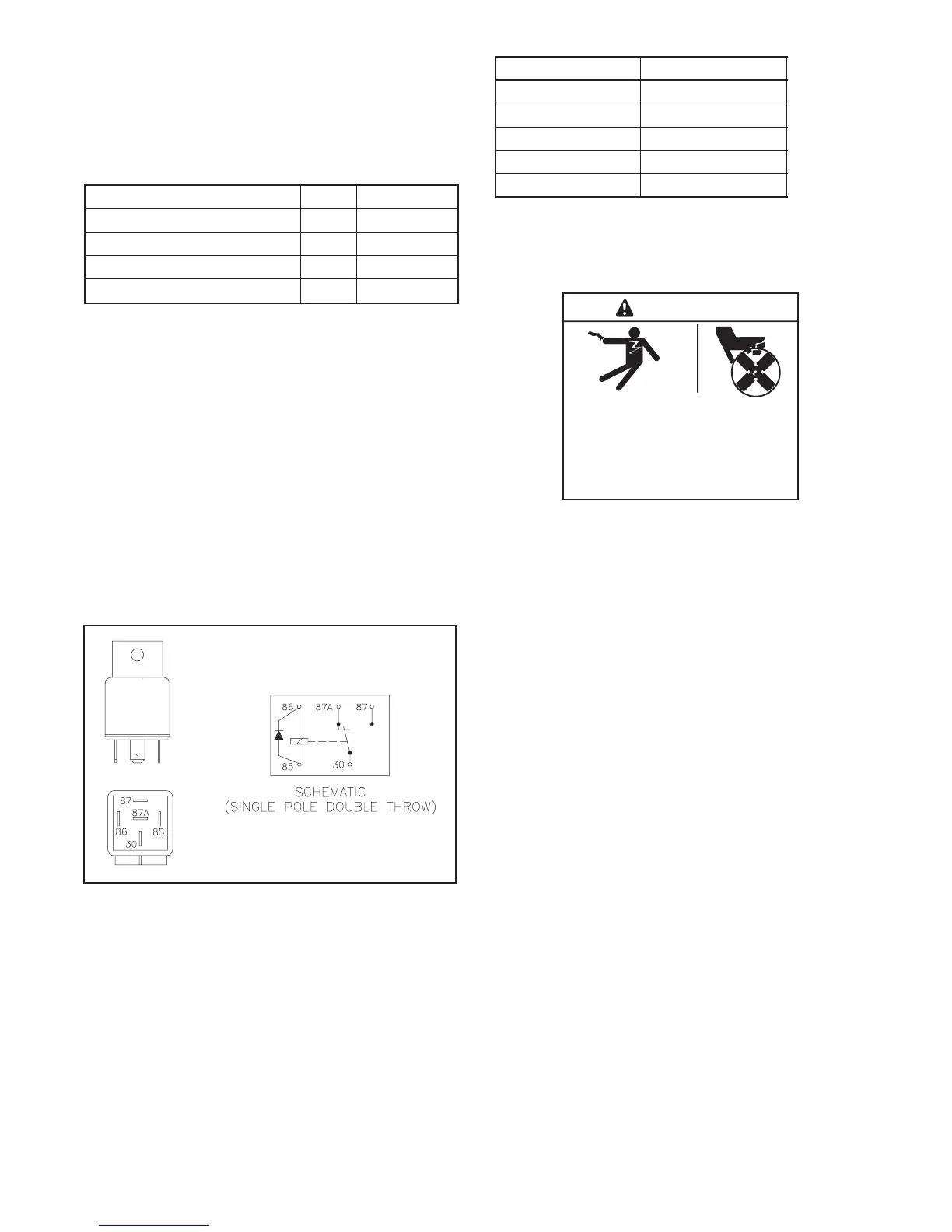
6.14 Starter Relay
The starter relay contains an internal diode across the
relay coil. See Figure 6-42. Continuity checks across
the coil terminals will show continuity (low resistance) in
one direction and an open circuit in the other.
Figure 6-43 shows the starter relay connections.
259391
Figure 6-42 Starter Relay
Relay Terminal Lead
30 14P
85 N7
86 71
87 14S
87A NC
Figure 6-43 Starter Relay Connections
6.15 Continuity Checks
Hazardous voltage.
Can cause severe i njury or death.
Operate the generator set only when
all guards and electrical enclosures
are in place.
Moving parts.
WARNING
Short circuits. Hazardous voltage/current can cause
severe injury or death. Short circuits can cause bodily injury
and/or equipment damage. Do not contact electrical
connections with tools or jewelry while making adjustments or
repairs. Remove all jewelry before servicing the equipment.
 Loading...