TP-6196 10/0994 Section 6 Component Testing and Adjustment
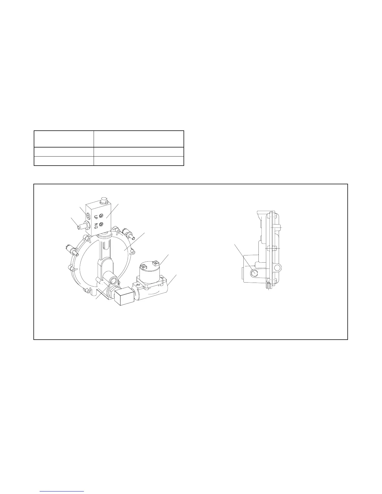
The fuel lock-off prevents fuel flow when the engine is
not operating. See Figure 6-35. Do not try to adjust the
fuel pressure, fuel mixture, or engine speed using the
fuel lock-off.
Checking the Fuel Pressure
Use a gauge or manometer to check the fuel pressure at
the secondary regulator inlet. See Figure 6-35.
Measure the fuel pressure with the generator set
running at rated load. Verify that the fuel pressure is
within the range shown in Figure 6-34. Contact the fuel
supplier if the inlet pressure is not within the specified
range.
Fuel Type
Supply Pr essure
kPa (in. water column)
Natural Gas 1.2--2.7 (5--11)
LP 1.7--2.7 (7--11)
Figure 6-34 Fuel Supply Pressure
6.12.4 Fuel Conversion
The multi-fuel system allows conversion from natural
gas to LP vapor (or vice-versa) in the field while
maintaining emissions-standard compliance. A trained
technician or authorized distributor/dealer can convert
the fuel system.
Two fuel connections on the fuel metering valve allow
field conversion between natural gas and LP vapor. The
fuel metering valves are factory-set and sealed to
comply with applicable emission standards and to
provide the best possible hot and cold starting.
TP-6196
2
1. Hose fitting
2. Plug
3. Fuel metering valve (factory-sealed, do not adjust)
4. Secondary regulator
5. Fuel solenoid valve
6. Fuel inlet, 1/2 in. NPT
7. Fuel lockoff (do not adjust)
8. Inlet pressure check location
3
1
7
6
8
4
5
Regulator, Side View
Figure 6-35 Fuel Regulator, Fuel Metering Valve, and Fuel Solenoid Valve
 Loading...