142 Section 8 Component Testing and Adjustment TP-6356 4/12
GM59925-
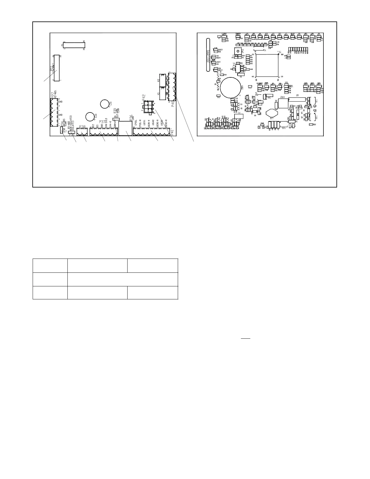
1. P40, 6-pin Common fault and horn dry contacts
2. P42, 6-pin Keyswitch (RSA II with ATS only)
3. P41, 8-pin Input (EPS/User) connections
4. P36, 8-pin CAN (factory only)
5. P35, 3-pin CAN termination (in/out) (factory only)
6. P37, 6-pin Power/CAN connections
1
3
Top ViewBottom View
7. P38, 2-pin DC power supply (+/--) connections
8. P39, 3-pin Isolated/non-isolated jumper
9. P34, 3-pin RS-485 termination resistor for last device
10. P27, 6-pin RS-485 connections
11. P11, 24-pin Ethernet connections (future use)
456789
10
11
2
Figure 8-33 RSA Circuit Board GM59925 Connectors
The RSA II connected to the controller MUST be
assigned as the RSA II master. See Figure 8-34 for a
summary of the EPS Supplying Load (ATS)
annunciation sources.
Note: The EPS feature does not apply to
Decision-Makerr 3000 controller.
Source DEC 3+ Controller
DEC 550/DEC 6000
Controllers
Local
(hard wired)
RSA II connection to the ATS
Remote
(RS-485)
Communication module
board connection to ATS
Controller connection
to A TS
Figure 8-34 EPS Supplying Load (ATS) Annunciation
Sources
Use the SiteTecht software to select either that the
generator set controller activates EPS Supplying Load
LED or the transfer switch activates LED or local EPS
supplying load.
Use the SiteTecht software to select for high speed
mode for direct connection to the Decision-Maker r 550
and 6000 controllers. Select lower speed for network
connection with the Modbusr/Ethernet converter. The
lower speed allows network functionality reducing loss
of communication faults.
8.17.2 Terminating Resistor
Each RSA II is shipped with a termination resistor in the
IN position on P34 connector. Determine the position of
the termination resistor in P34 connector based on the
following two applications.
RSA II Master only. Verify that the termination resistor
is in the IN position on P34 connector on the RSA II
master.
RSA II Master with RSA II Slaves. Verify that the
termination resistor is in the IN position on P34
connector on the last
RSA II slave in the daisy chain
connection. Place the termination resistor in the OUT
position on P34 connector on the RSA II master and all
RSA II slaves except the last RSA II slave.
Modbusr is
registered trademark o
Schneider Electric.
 Loading...


