59Section 3 Decision-Makerr 3+ TroubleshootingTP-6356 4/12
3.6.5 Controller Speed Sensor Circuitry
To check the controller’s ability to respond to signals
from the speed sensor, perform the following test:
1. Move the generator set master switch to the
OFF/RESET position.
2. Move the FASTCHECK
®
engine switch to the OFF
position.
3. Move the generator set master switch to the RUN
position. Verify that the IGN., CRK., and REG.
lamps light.
4. Within 5 s econds, move the FASTCHECK
®
engine
switch to the RUN position.
5. If the CRK. lamp goes out on the FASTCHECK
®
,
the controller speed sensor circuitry functions
correctly.
3.6.6 Generator Set Condition Indicator
Terminal (TB1 Terminal Strip)
Connect the remote accessories (audiovisual alarm,
remote annunciator, dry contact kits, etc.) to the
controller’s TB1 terminal strip to signal the condition of
the generator set. Some generator sets may not have
the optional sending devices necessary to operate all
the generator set condition indicators.
If the remote accessories will not operate, test for output
voltage at the TB1 terminal strip. To test the operation of
each indicator, move the generator set master switch
and FASTCHECK
®
toggle switch to the position
prescribed.
The test point voltage is slightly lower than the voltage
supplied to the controller (12 or 24 volts). If the correct
voltage is not detected at the test point, remote
accessories (audiovisual alarm, remote annunciator,
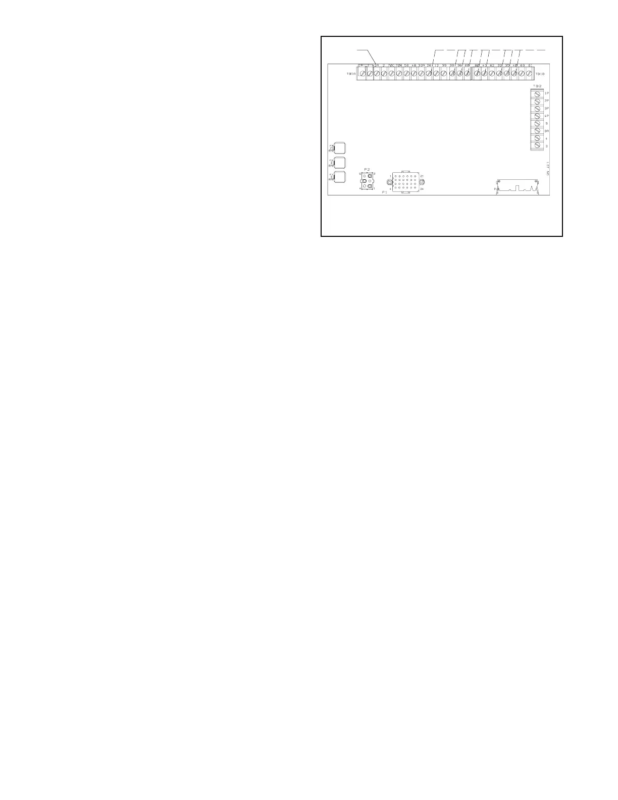
dry contact kits, etc.) will not function. Figure 3-26 and
Figure 3-27 show test point connections.
GM28725-D
1. TB1-42A
2. TB1 (TB1A) and TB3 (TB1B) (see Section 3.6.6, Generator
Set Condition Indicator Terminal)
1
2
Figure 3-26 Indicator Lamp Test Connections on the
Main Circuit Board
When checking the controller test point voltage, place
the negative (--) lead of the voltmeter on the terminal
designated in the chart and the voltmeter positive (+)
lead on TB1-42A.
Because of the absence of AC output, the auxiliary lamp
flashes during controller testing. The NOT IN AUTO
lamp illuminates whenever the generator set master
switch is not in the AUTO position.
1. Leave the FASTCHECK
®
engine switch in the
RUN position for at least 30 seconds before
pushing the toggle switches.
2. Move the generator set master switch to the
OFF/RESET position.
3. Move the FASTCHECK
®
engine switch to the OFF
position.
4. Move the generator set master switch to the RUN
position. Verify that the IGN., CRK., and REG.
lamps light. Within 5 seconds, move the
FASTCHECK
®
engine switch to the RUN position.
 Loading...


