150 Section 8 Component Testing and Adjustment TP-6356 4/12
Fast-Responset III, Wound Field Design
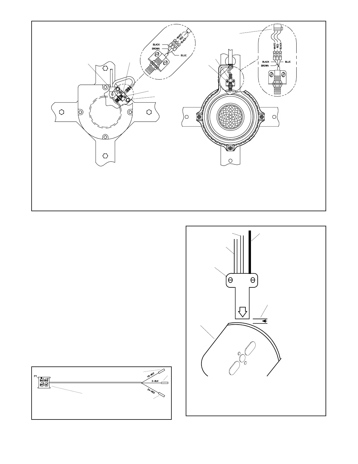
GM39354-D
1. Loop shielded cable through mounting clamp and make loop extend 10 mm (0.38 in.) below mounting clamp
2. Speed sensor
3. Speed sensor (three hole) bracket (#4--40 x 0.25 in. pan head screws)
4. Bracket (four hole) (#10--24 x 0.625 in. hex head screws)
5. Speed sensor (three hole) bracket (M3--0.50 x 8 mm pan head screws)
6. Attach cable tie near end of shielded cable to prevent cable from pulling through grommet
1
2
3
4
Fast-Responset II, PMG Design
2
5
6
Figure 8-51 Existing Speed Sensor and Mounting Designs
b. Mount the new speed sensor using the original
screws, do not final tighten the screws at this
time.
c. Locate the existing generator set wiring
harness with three female pushon terminals.
Cut off each terminal and strip wire ends 9 mm
(3/8 in.).
d. Match the wire colors (white, black, and red)
and crimp the stripped wire ends to the speed
sensor harness GM70485. See Figure 8-52.
e. Plug the speed sensor connector (Figure 8-50,
Item 6) in the speed sensor harness connector
(Figure 8-52, Item 4). Each connector is keyed
to mate only one way.
f. Loosen the adjustment screws (Figure 8-50,
Item 3) and adjust the air gap using a feeler
gauge and specifications from Figure 8-53.
Final tighten the adjustment screws.
1. Wire 16: white
2. Wire 2: black
3. Wire 24: red
4. Connector
GM51395-A
2
3
4
1
Figure 8-52 Speed Sensor Harness GM70485
0 + ---
0.36--0.71 mm
(0.014--0.028 in.)
TP-5353-8
1. Speed sensor
2. Wire 16: white/clear
3. Wire 24: red
4. Wire 2: black
5. Air gap: 0.36--0.71 mm (0.014--0.028 in.)
6. Magnetic actuator (PMG model shown)
1
2
3
4
5
6
Figure 8-53 Speed Sensor Air Gap
 Loading...


