41Section 3 Decision-Makerr 3+ TroubleshootingTP-6356 4/12
A-336432/Y-5246-S
AOP Anticipatory (Low) Oil Pressure
AUX. Auxiliary
AUX PRE Auxiliary Prealarm (see HBV)
AHET Anticipatory High Engine Temperature
AWT Anticipatory (High) Water Temperature
BCF Battery Charger Fault
EAD Engine Air Damper
ES Emergency Stop
FS Fuel Solenoid
HBV High Battery Voltage (was Aux. Prealarm
HET High Engine Temperature
HWT High Water Temperature
LBV Low Battery Volts
LF Low Fuel
LOP Low Oil Pressure
LWT Low Water Temperature
NIA Not In Auto
OC Overcrank
OS Overspeed
SG Safeguard Circuit Breaker
SYS RDY System Ready
WLS Water Level Switch
Input
Output
SYS
RDY
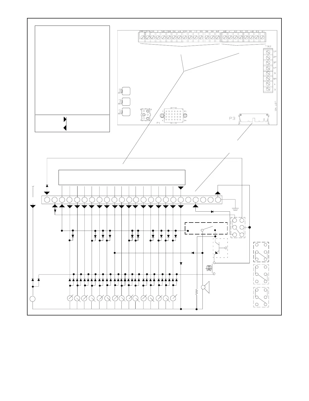
Controller 16-Light LED Indicator Panel Circuit Board
BC
TB1--26
TB1--12
TB1--39
TB1--38
TB1--36
12V REG.
OC
OS
LOPHET
Alarm Horn
Lamp Test
Horn
Silence
Grd.
Run
Auto
Off/Reset
Generator Set
Master Switch
Positions
AUTO
OFF/
RESET
RUN
TB1--48
ES
AUX
TB1--60
AOP
LWT
LBVLF NIA
T27
HBV/AUX PRE
Controller Main Circuit B oard Terminal Strips TB1(TB1A) and TB3 (TB1B)
P4
123456789101112131415161718192021222324
EAD
TB1--56
AHET
On
6
5
4
3
2
1
12 3
Alarm Horn Switch
1
2
Cable connection between
Controller Main Circuit B oard P 3 and
16-Light LED Indicator Panel Circuit Board P4
Controller Main Circuit B oard
TB3--32
TB3--63
TB3--61
TB3--62
TB3--41
TB3--35
TB3--80
TB3--40
TB1 (TB1A)
TB3 (TB1B)
Figure 3-6 Controller to 16-Light LED Indicator Panel Circuit Board -336432 Connections P3
 Loading...


