18 TT-1625 7/17
Use solid or stranded 14-22 gauge wire. To determine
the wire gauge, measure the cable distance between
the controller and master RSA III.
For example, if the cable distance between the
controller and the master RSA III is 122 m (400 ft.), then
the total wire length for each conductor is 122 m
(400 ft.). According to the chart in Figure 19, this
example requires 22-gauge wire.
Throughout step 6, refer to the following illustrations.
See Figure 20 for RSA III circuit board c onnectors. See
Figure 41 for RSA III circuit board terminal connections.
See Figure 57 to Figure 63 for the RSA III wiring
diagrams and Figure 64 and Figure 65 for the
RSA III interconnection diagrams.
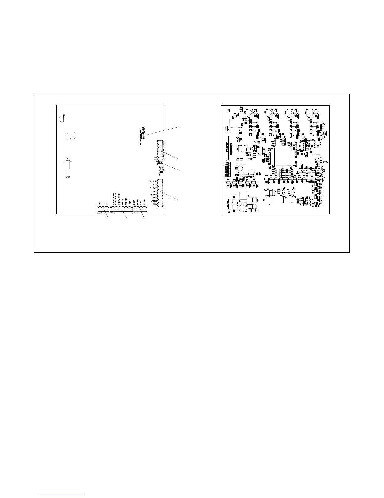
GM86125-
1. P39, 3-pin Isolated/non-isolated jumper
2. P27, 6-pin RS-485 connections
3. P34, 3-pin RS-485 termination resistor for last device
4. P41, 8-pin Input (EPS/User) connections
1
2
3
Top ViewBottom View
4
567
5. P42, 4-pin Input user 4 & 5 connections
6. P40, 6-pin Common fault and horn dry contacts
7. P37, 3-pin Power/CAN connections
Figure 20 RSA III Circuit Board GM86125 Connectors
The RSA III has the following wiring and selections:
D P27, 6-pin RS-485 connections (communication
between controller and RSA III master). See
step 6.3.
D P27, 6-pin RS-485 connections (communication
between RSA III master and RSA III slaves). See
step 6.4.
D P34, 3-pin RS-485 termination resistor for last
device. See step 6.4.
D P37, 3-pin power/CAN connections. See step 6.5.
D P39, 3-pin isolated/non-isolated jumper. See
step 6.6.
D P40, 6-pin common fault and horn dry contacts. See
step 6.7.
D P41, 8-pin input (EPS/user) connections. See
step 6.8.
D P42, 4-pin input user 4 & 5 connections. See
step 6.11.
6.1 Deenergize the 12/24-volt DC power source to
each R SA III, if not already done.
6.2 Flush mount RSA III only. When using a
flush-mount RSA III box with a bushing, it is
recommended to run all wiring to the RSA III box
and then mount it to the wall or to the electrical
box in the w all. Check that box is square to the
wall; adjust as needed. After the RSA III box is
mounted, make the individual electrical
connections to the RSA III circuit board as
described in the following steps.
Position wall-mounting plate GM85126 against
the RSA III bezel GM85134 prior to attaching the
wiring.
 Loading...


