26 TT-1625 7/17
6.8 P41, 8-pin input (EPS/user) connections. See
Figure 20 for location of P41 on the RSA III. See
Figure 41 for P41 U ser Input 1--3 Connections.
See Figure 42 for P42 User Input 4--5
Connections (Decision-Makerr 3500 controllers
only).
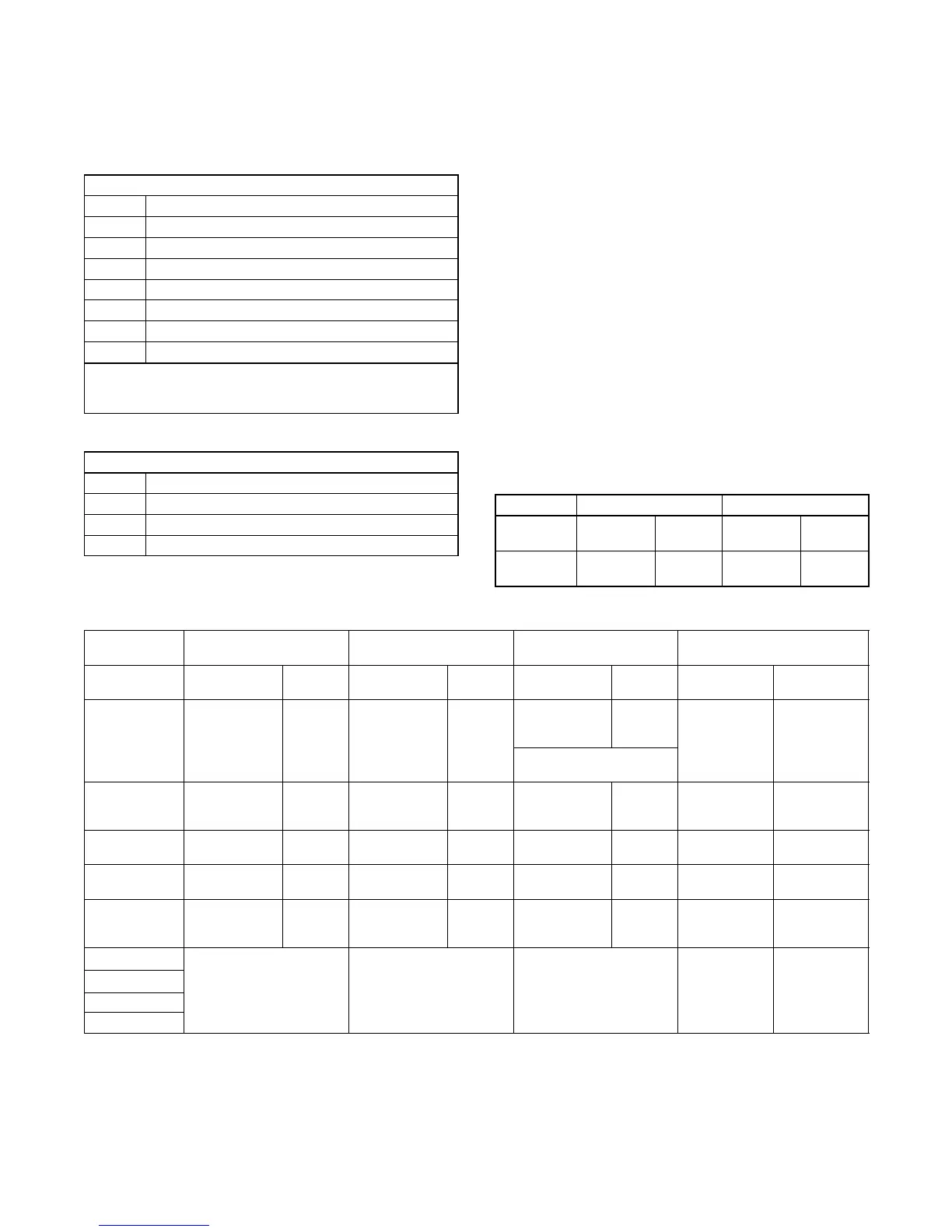
P41 Input/Connections
P41-1 Local ATS emergency on input *
P41-2 Local ATS emergency on input return *
P41-3 User input 1
P41-4 User input 1 return
P41-5 User Input 2
P41-6 User Input 2 return
P41-7 User Input 3
P41-8 User Input 3 return
* Applies to Decision-Makerr 3+ controller only. Supplied via
Modbusr RS-485 on the Decision-Makerr 550, 3000, 3500
controllers.
Figure 41 RSA P41User Input 1--3 Connections
P42 Connections
P42-1 User input 4
P42-2 User input 4 return
P42-3 User input 5
P42-4 User input 5 return
Figure 42 RSA P42 User Input 4--5 Connections
6.9 Make any additional local user-selected
connections to the RSA III P41 connector. User-
defined inputs can be used for any status,
warning, or shutdown including open circuit
breaker, air damper, etc. The user-selection
connections are defined in Figure 43 and
Figure 44 and include:
D User Input 1 (local).
D User Input 2 (local).
D User Input 3 (local).
D User Input 4 (local).
D User Input 5 (local).
D ATS emergency input (local). Connect wiring
from the user-supplied transfer s witch (ATS)
emergency position auxiliary contacts. See the
respective ATS wiring diagram(s).
Note: User-defined digital inputs #1 to #5 are
selected at the RSA III master only and
annunciated to the RSA III slave(s). No
user-defined digital input selection is
available at the RSA III slave(s).
Controller User Input 4 User Input 5
Master RSA
III (Local)
P42-1 user-
selectable
P42-2
(ground)
P42-3 user-
selectable
P42-4
(ground)
DEC 3500 TB1-DI 4
TB1-GND
or ground
TB1-DI 5
TB1-GND
or ground
Figure 43 RSA III Local P42 Input Connections
Controller User Input 1 User Input 2 User Input 3
ATS Emergency Aux. Contacts
for EPS Supplying Load Input
Master RSA III
(Local)
P41-3 user-
selectable
P41-4
(ground)
P41-5 user-
selectable
P41-6
(ground)
P41-7 user-
selectable
P41-8
(ground)
P41-1 on
RSA III
P41-2 (ground)
on RSA III
DEC 3+
TB5-10 on
comm. module,
user- selectable
TB5-4
(ground)
TB5-11 on
comm. module,
user- selectable
TB5-5
(ground)
TB5-12 on
comm. module,
user- selectable
TB5-6
(ground)
TB5-9 on
comm. module
and then to
P41-8 on
RSA III
TB5-3 on
comm. module
and then to
P41-7 (ground)
on RSA III
Also used for high battery
voltage on comm. module
DEC 550
TB4-7 (D7)
user-selectable
using Menu 9
TB4-28
(ground)
TB4-8 (D8)
user-selectable
using Menu 9
TB4-29
(ground)
TB4-10 (D10)
user-selectable
using Menu 9
TB4-31
(ground)
via RS-485 via RS-485
DEC 3000 TB1-DI 1
TB1-GND
or ground
TB1-DI 2
TB1-GND
or ground
TB1-DI 3
TB1-GND
or ground
via RS-485 via RS-485
DEC 3500 TB1-DI 1
TB1-GND
or ground
TB1-DI 2
TB1-GND
or ground
TB1-DI 3
TB1-GND
or ground
via RS-485 via RS-485
DEC 6000
TB4-7 (D7)
user-selectable
using Menu 9
TB4-28
(ground)
TB4-8 (D8)
user-selectable
using Menu 9
TB4-29
(ground)
TB4-10 (D10)
user-selectable
using Menu 9
TB4-31
(ground)
via RS-485 via RS-485
MPACr 750
Main logic board input #1 Main logic board input #2 — via RS-485 via RS-485
MPACr 1000
MPACr 1200
MPACr 1500
Figure 44 RSA III Local P41 Input Connections
 Loading...


