TT-1625 7/17 27
6.10 APM802 Controllers only. For the user-defined
digital inputs 1 to 5 on the RSA III, use the
controller digital inputs connections located on
TB10. After the RSA III installation is complete,
these digital inputs are selected with SiteTecht
software under the Product Connection Inputs
menu. Refer to the wiring d iagram manual to
determine the connections on TB10 and
Figure 45 to determine the digital input
designations.
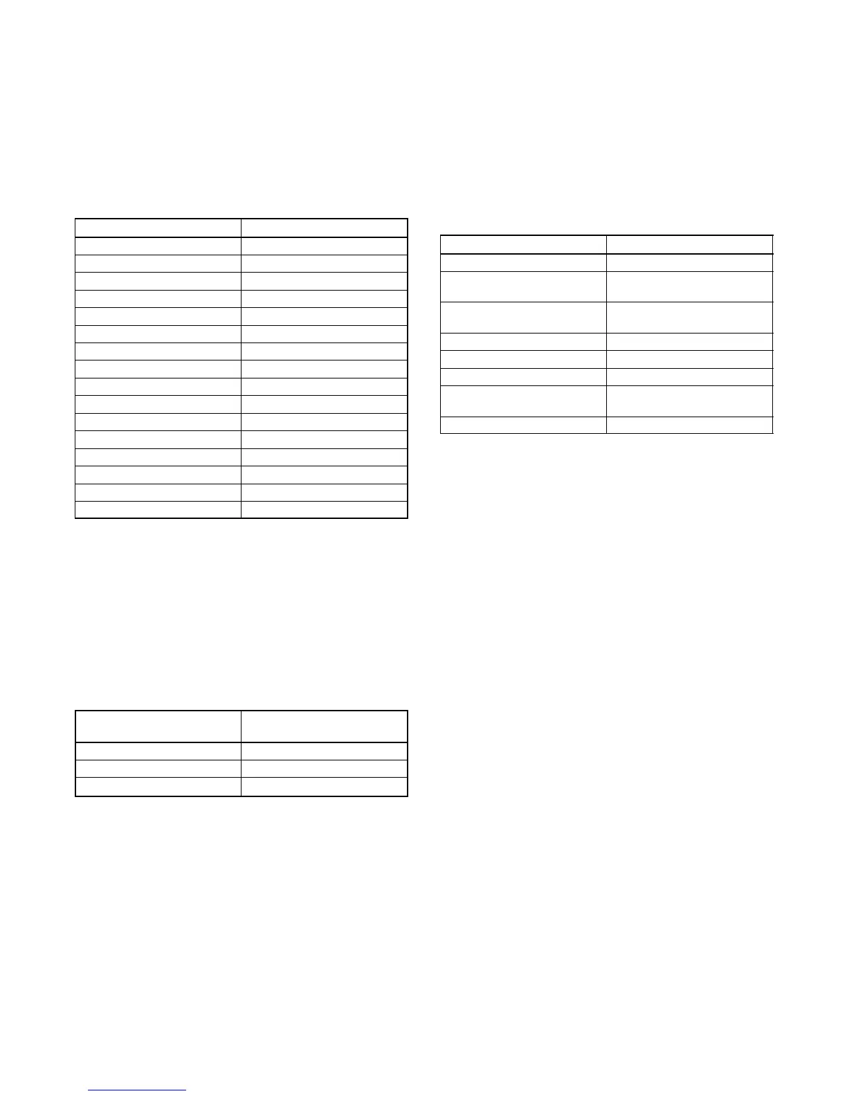
Digital Inputs Designation
Digital Input 1 Low Fuel Level Switch
Digital Input 2 Breaker Open Status
Digital Input 3 Remote Reset
Digital Input 4 Aux Shutdown
Digital Input 5 High Fuel Level Switch
Digital Input 6 Aux Warning
Digital Input 7 Low Oil Level
Digital Input 8 Battery Charger Fault
Digital Input 9 Fuel Leak Alarm
Digital Input 10 Idle Mode
Digital Input 11 GFCI Tripped
Digital Input 12 Remote Speed Adjust Enable
Digital Input 13 Key Switch Enable
Digital Input 14 Load Shed Enable
Digital Input 15 Overcrank Test
Digital Input 16 Reserved for Factory Use
Figure 45 Digital Inputs on APM802 Controller
6.11 DEC 550 and DEC 6000 Controllers only. The
RSA III user inputs 1--3, when in the remote
connection, are tied to the controller digital
inputs. See Figure 46.
If required, the user-input selection tied to digital
inputs D7, D8, and/or D10 can be changed using
Menu 9, Input Setup. Refer to the DEC 550
(TP-6200) or DEC 6000 (TP-6750) controller
operation manual as needed.
RSA III User Inputs
(Remote)
Tied to DEC 550 and 6000
Controller Digital Inputs
1 D7
2 D8
3 D10
Figure 46 RSA III Remote User Inputs with DEC 550
and DEC 6000 Controllers
6.12 DEC 8000 Controllers only. For the
user-defined digital inputs 1 to 5 on the RSA III,
use the controller binary inputs connections
located on the customer connection block, TB1.
After the RSA III installation is complete, these
digital inputs are selected with SiteTecht
software under the Product Connection Inputs
menu. Refer to the wiring d iagram manual to
determine the connections on TB1 and to
Figure 47 to determine the binary input
designations and functionality.
Binary Inputs Default Definitions
Binary Input 1 Auxiliary Fault Shutdown
Binary Input 2 Auxiliary Warning --
Always/Anytime
Binary Input 3 Auxiliary Warning --
Running Only
Binary Input 4 Low Coolant Level
Binary Input 5 Ground Fault Detected
Binary Input 6 Remote Fault Reset
Binary Input 7 Remote Generator Circuit
Breaker Button (close/trip)
Binary Input 8 Auxiliary Slow Stop
Figure 47 Binary Inputs on DEC 8000 Controller
6.13 Document the user-selected inputs for future
reference. If user-selected inputs 1 to 5 (remote)
are used, the user may add the identification on
the RSA III front panel strip. Use a black
permanent marker on the respective white blank
box to identify the user input. The user can also
fill in the generator ID location information if
needed. Allow the marker ink to dry before
handling the RSA III front panel.
Other methods for adding the information to the
identification strip would be to use a PC and print
the information on an adhesive label or use a
label maker. The print font on the RSA III front
panel is Myriad bold 10 point. Attach the printed
label(s) to the white blank boxes on the RSA III
front panel.
 Loading...


