28 TT-1625 7/17
6.14 The RSA III connected to the controller MUST be
assigned as the RSA III master. See Figure 48
for a summary of the EPS Supplying Load (ATS)
annunciation sources.
Note: Does not apply to DEC 3000 controllers.
Source DEC 3+ Controller
DEC 550/DEC 6000
Controllers
Local
(hard wired)
RSA III connection to the ATS
Remote
(RS-485)
Communication module
board connection to ATS
Controller connection
to ATS
Figure 48 EPS Supplying Load (ATS) Annunciation
Sources
Use the SiteTecht software to select either that
the generator set controller activates EPS
Supplying Load LED or the transfer switch
activates LED or local EPS supplying load.
Use the SiteTecht software to select the high
speed mode for direct connection to the D EC 550
and DEC 6000 controllers. Select lower speed
for network connection with the Modbusr/
Ethernet converter. The lower speed allows
network functionality reducing loss of
communication faults.
6.15 Replace the controller cover and hardware on the
DEC 550 and DEC 6000 controllers and the
access panels on the DEC 8000 and APM802
controllers.
7. Complete the RSA III final installation.
Proceed to either Step 7.1, Surface mount RSA III final
installation, or Step 7.2, Flush mount RSA III final
installation.
7.1 Surface mount RSA III final installation.
7.1.1 Mount the RSA III box to the wall or to the
electrical box in the wall if not already
done. Check that the box is square to the
wall; adjust as needed.
7.1.2 Position the RSA III front panel assembly
to the surface-mount box and install four
self-tapping screws X-67-154. Do not
tighten the screws.
7.1.3 C enter the remote annunciator in the box
and square with the wall. Tighten the
screws.
7.1.4 Proceed to step 8.
7.2 Flush mount RSA III final installation.
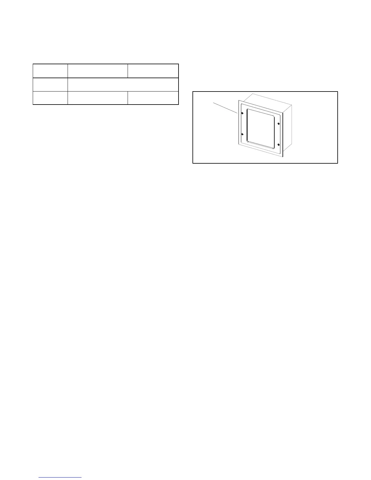
7.2.1 Place wall-mounting plate GM85126
behind the RSA III front panel assembly
flange if not already done. See Figure 49.
Note: The wall-mounting plate can be installed
behind the RSA III front panel assembly
flange even if RSA III front panel assembly
is already wired.
ADV-8661
1. Wall-mounting plate GM85126
1
Figure 49 RSA III Wall-Mounting Plate
7.2.2 Align the holes of the wall-mounting plate
with the RSA III front panel assembly to
the surface-mount box and install four self-
tapping screws X-67-154. Do not tighten
the screws.
7.2.3 C enter the remote annunciator in the box
and position wall-mounting plate square
with the wall. Tighten the screws.
7.2.4 Proceed to step 8.
 Loading...


