Product description Service and Repair Manual
Technical description
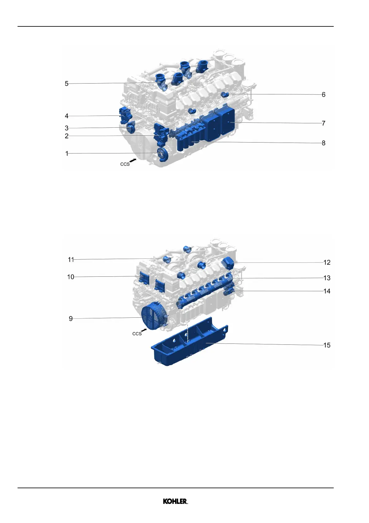
Fig. 2: Diesel engine / view from the damper side
CCS Engine front (vibration damper side) 5 Exhaust gas connection
1 Water pump high temperature 6 Lifting lug
2 Thermostat housing high temperature 7 Oil cooler
3 Water pump low temperature 8 Oil filter cartridge
4 Thermostat housing low temperature
Fig. 3: Diesel engine / view from the damper side
CCS Engine front (vibration damper side) 12 Cylinder head cover
9 Vibration damper cover 13 Charge air pipe
10 Engine control unit - ECU 14 Starter
11 Straight air intake 15 Oil pan
1.1.1 Cylinder designation, direction of rotation
Principle according to ISO 1204
Cylinder 1 is located on flywheel side. Direction of rotation as shown on the flywheel side.
18
© 2021 by Kohler Co. All rights reserved.
KD83V16 33525088901_2_1 EN_US
2021-07
 Loading...