TT-1625 7/17 11
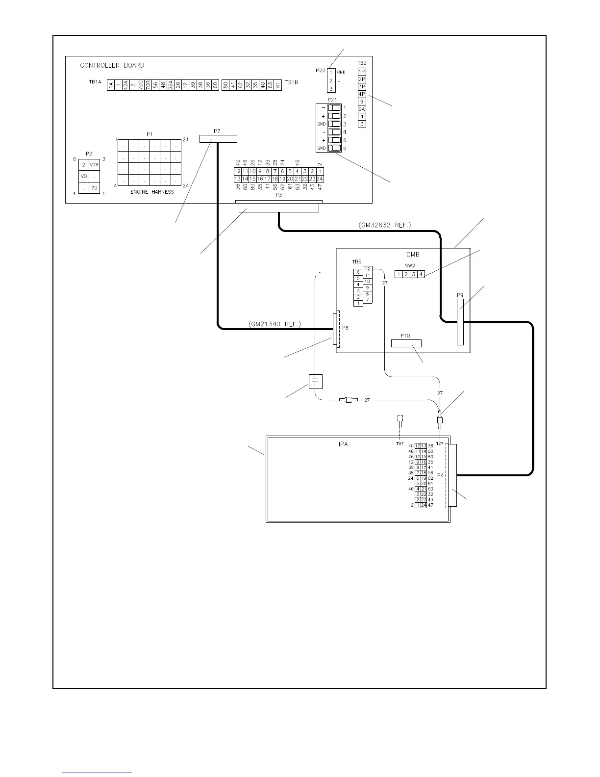
CMB—Communication Module Board
IPA—Indicator Panel Assembly
(P#)—Plug
TB1, TB2—Controller Board Terminal Block
TB5—Communication Interface Board Terminal Block
1. P22 CAN (engine) communication connection
2. DEC 3+ controller main circuit board
3. P21 RS-485 communication connection for remote serial annunciator
4. Communication module board GM49791-1
5. SW2 DIP switch; place SW2-1 in closed position when paralleling REOZV/B/C models
6. 24-position ribbon cable GM32632 to comm. module board
7. P10 used only when GM49791 -2 gauge driver board was previously installed; connect P10 to the communication module board
to drive coolant temperature and oil pressure gauges on the DEC 3+ controller
8. Lead GM35318 connecting T27 on indicator panel to user input 3 on c omm. module board for high battery voltage
9. 24-position ribbon cable GM32632 to indicator panel
10. Controller indicator panel circuit board on the RSA
11. Optional battery charger with HBV alarm contacts
12. 10-position ribbon cable GM21340 to comm. module board
13. 24-position ribbon cable GM32632 to main circuit board
14. 10-position ribbon cable GM21340 to main circuit board
GM32644-F
2
13
4
6
9
10
12
14
8
Legend
11
3
1
7
5
Figure 9 Communication Module Schematic, DEC 3+ Controller
 Loading...