TT-1625 7/17 21
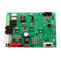
DEC 3000 Controller. Figure 29 shows the
DEC 3000 controller with P21 location and
Figure 30 shows the RS-485 connections.
1. Main logic circuit board
2. P21 for RSA III RS-485 communication connection
GM65741-
1
2
Figure 29 DEC 3000 Controller R S-485 Connectors
P21
Connector
Circuit Board
Designation
Wire
Designation
P21-1 GND Shield
P21-2 (+) White
P21-3 (--) Black
P21-4 GND Shield
P21-5 (+) White
P21-6 (--) Black
Note: When using RS-485 communication cable, connect the
“shield” wire at either end but not at both ends.
Figure 30 DEC 3000 P21 R S-485 Connections
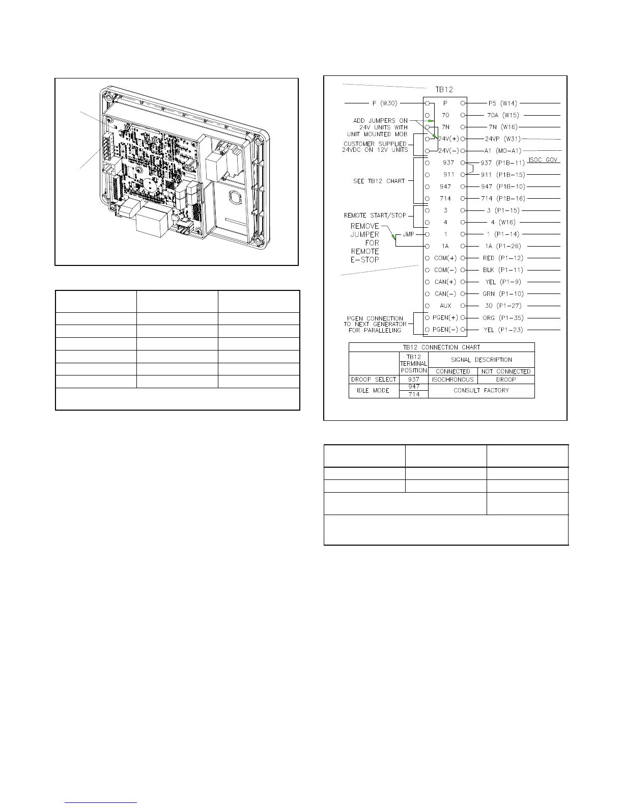
DEC 3500 Controller. Figure 31 shows the
DEC 3500 controller with TB12 location and
Figure 32 shows the RS-485 connections.
1. TB12 connection located on the generator set
2. RS-485 communication connections to RSA III (master)
TT-1625
1
2
Figure 31 DEC 3500 Controller R S-485 Connectors
TB12
Connector
Circuit Board
Designation
Wire
Designation
COM (+) (+) White
COM (--) (--) Black
Do not connect at TB12 or DEC 3500,
tape to insulate unused end.
Shield
Note: When using RS-485 communication cable, connect the
“shield” wire at the RSA III P27 connection but not at the
DEC 3500 controller/TB12 connection.
Figure 32 DEC 3500 TB12 RS-485 Connections
 Loading...