©
B
R
E
A
T
H
E
S
A
F
E
2
0
1
9
www.breathe-safe.com.au
Page
8
Issue date:
Controlled document:
Revision:
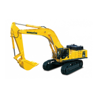
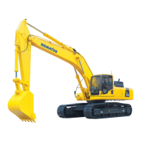
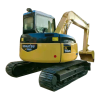
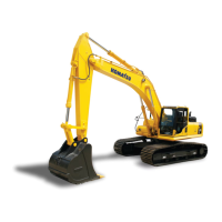
WA900-3EO
The components, which combine to make up
the air conditioning system, are in four dierent
circuits as under:
» Air Circuit
» Refrigeration Circuit
» Heating Circuit
» Electrical Circuit
AIR CIRCUIT
The evaporator section has a basic air
recirculation circuit provided by two forward
curved fans in parallel. These blow air through
the evaporator and deliver the conditioned air
into the cab.
Average cab temperature is controlled by a
thermostat, the capillary of which senses the
temperature of the coil.
A second circuit is created by the addition of a
lter / pressuriser. If tted this consists of two
stages of ltering, followed by a single stage
pressurising fan with the ltered fresh air being
mixed with cab return air before passing over the
heat exchange coils.
Depending on the model of condenser, the
condenser air is provided by either one axial
(propeller) ow fan and drawn through the
bottom of the condenser coil and discharged
through the top of the condenser. Or the
condenser air is provided by three axial fans
and drawn through the top of the condenser and
discharged over the condenser coil.
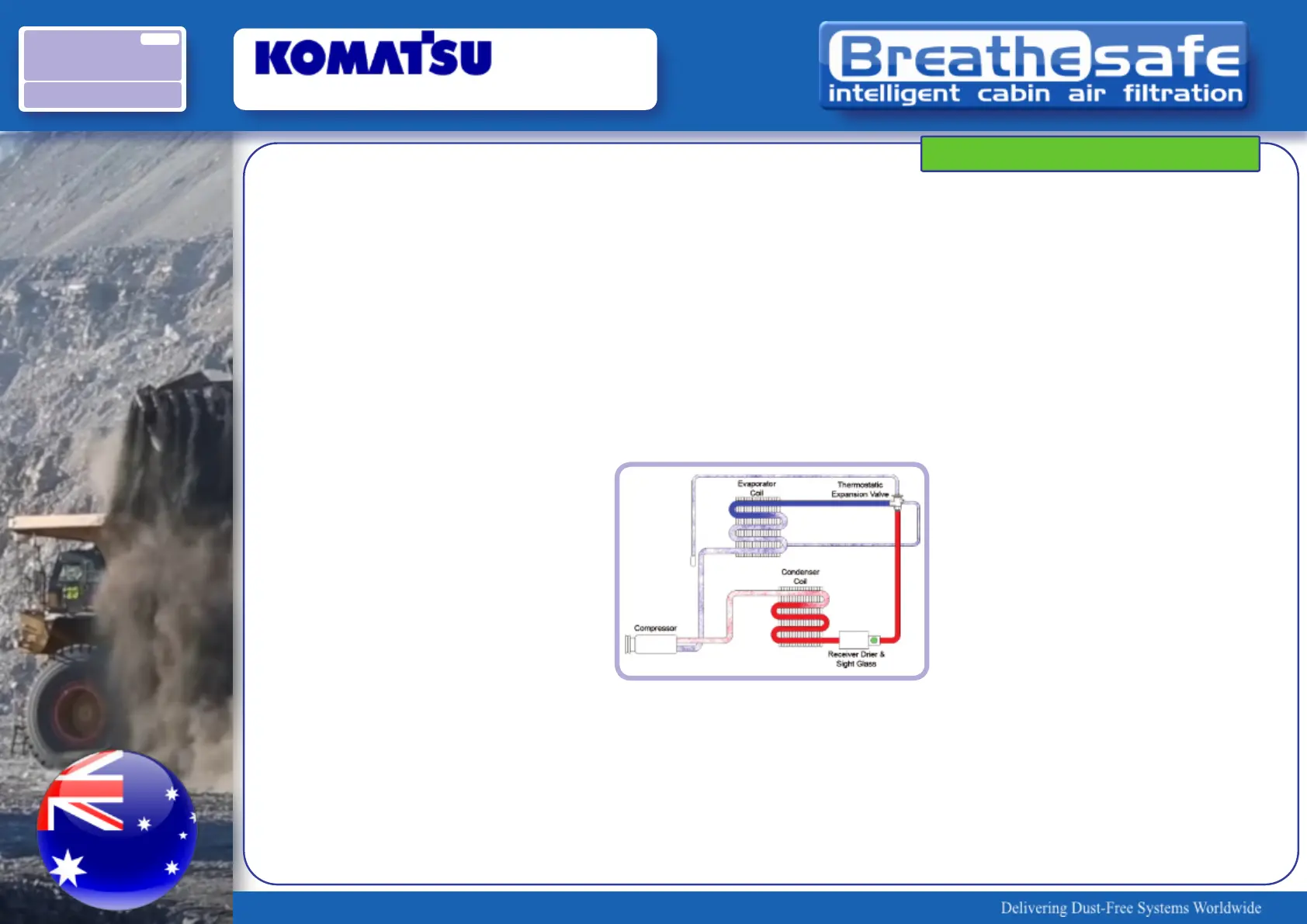
REFRIGERATION CIRCUIT
To illustrate the change of state of the
refrigerant as it travels through the system, the
descriptions of the refrigeration components
have been listed in the order which coincides
with refrigerant ow.
1. Condenser Coil
Condensing of the refrigerant is the change
of state of the refrigerant from a vapour to a
liquid. The condenser
receives the high pressure, high
temperature refrigerant vapour from the
compressor and condenses it to a high
temperature liquid. The liquid refrigerant
then ows to the receiver drier.
2. Receiver Drier
The receiver drier utilised in these units is
of fully welded construction, tted with an
integral sight glass. The receiver drier
serves as a reservoir for the storage of high
pressure liquid produced in the condenser.
It also functions as a lter/drier by means
of a dehydrating agent combined with
ltration system to trap minute particles of
moisture and foreign material which may
have entered the refrigeration system.
3. Thermostatic Expansion Valve
The expansion valve is located on the
evaporator inlet line and provides the
functions of throttling and controlling the
ow of liquid refrigerant to the evaporator
coil. This refrigerant ow is restricted
creating a pressure drop across the valve.
Thus, the refrigerant that enters the valve
as a hot high pressure liquid exits it as a
cold low pressure liquid.
The ow rate will vary according to the
heat load, sensed by the diaphragm
capillary, and the suction pressure at the
evaporator.
PRINCIPALS OF AIR CONDITIONING
OVERVIEW
 Loading...