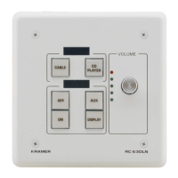
3.2 The RC-63DLN Room Controller Rear Panel
This section defines the rear panel of the RC-63DLN.
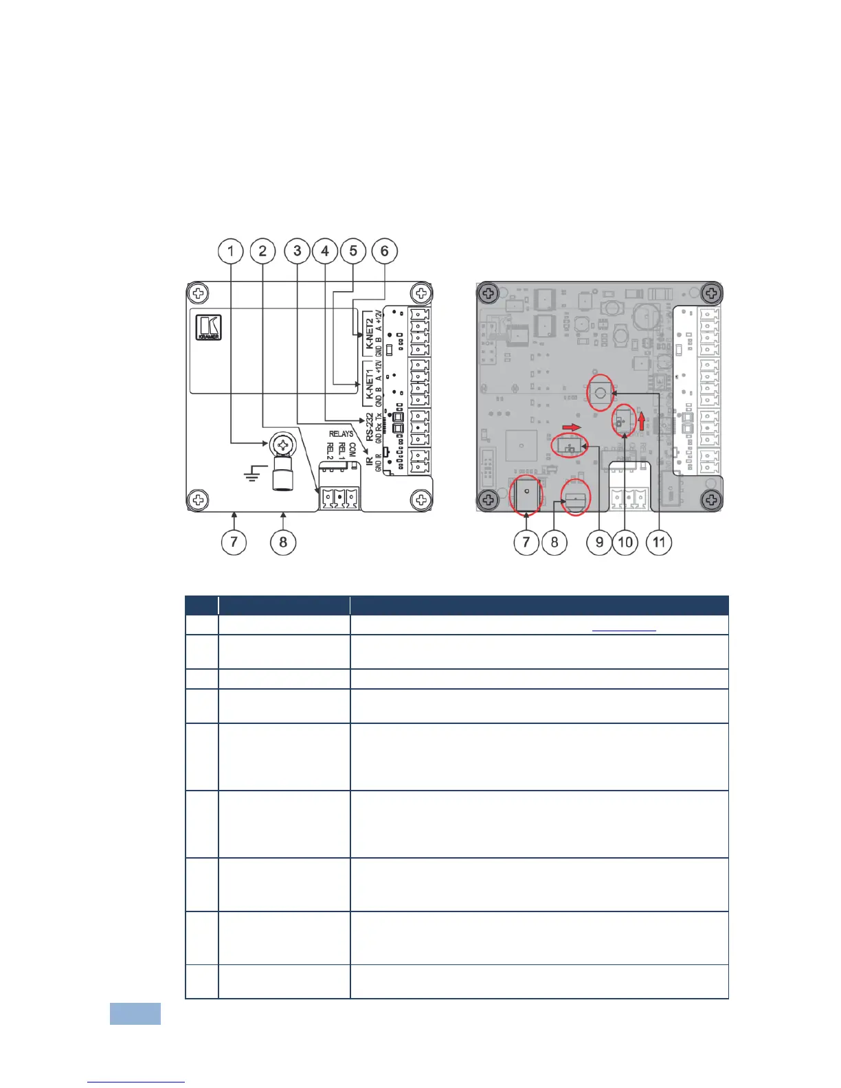
3.2.1 The RC-63DLN Rear Panel Version for the USA
This section shows the rear panel of the RC-63DLN USA version.
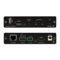
Figure 2: RC-63DLN Rear Panel for the USA
Connect to grounding wire (optional), see Section 4.3
2 relay connections (REL 1 and REL 2). Connect to room items
(such as lighting, screen settings, and so on)
Control a machine via an IR Emitter
RS-232 Port (GND,
Rx, Tx)
Connect to the RS-232 connector on the A/V equipment or a PC
or other serial controller
Connect the GND pin to the Ground connection; pin B (-) and pin
A (+) are for RS-485, and the +12V pin is for powering the unit
The ground connection is sometimes connected to the shield of the
RS-485 cable
Connect the GND pin to the Ground connection; pin B (-) and pin
A (+) are for RS-485, and the +12V pin is for powering the unit
The ground connection is sometimes connected to the shield of the
RS-485 cable
Connect to a computer for firmware upgrade or setting the
K-NET ID number
The USB port is accessible from the side
IR IN built-in IR
Receiver
Use to learn the IR commands from a machine’s remote control
transmitter
The IR receiver is accessible from the side
For technical support use only (should be set to the right in the
direction of the arrow for normal operation)
 Loading...