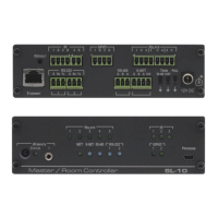
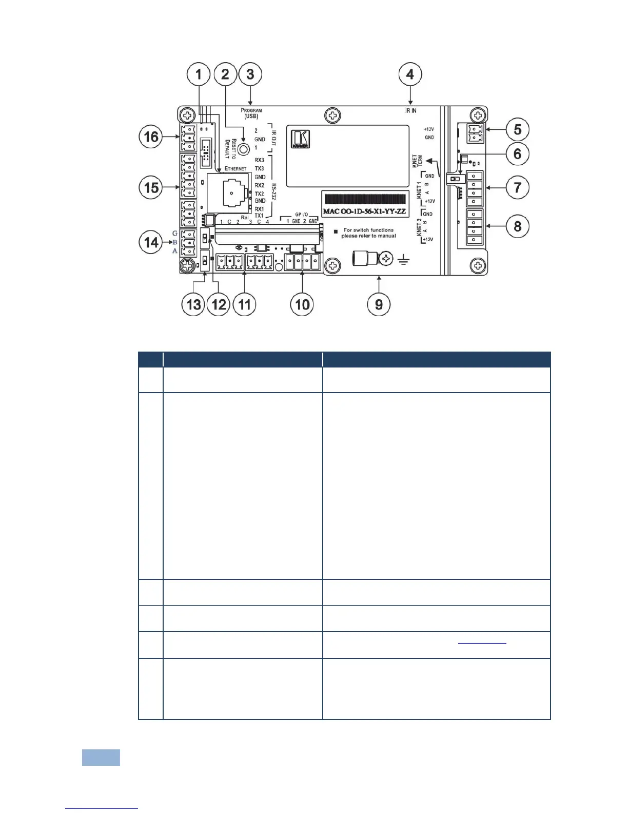
Figure 2: RC-74DL Master Room Controller - Rear
Connects to the PC or other serial controller
through computer LAN
Caution: The current LCD text and all button
actions are erased
This operation should be carried out by authorized
Kramer technical personnel or by an external system
integrator, and requires removal of the device from
the wall by unscrewing the four wall mount screws
Using a small screwdriver, push to erase all custom
programming and reset to the factory default
definitions:
Disconnect the power and then connect it while
pressing the Factory Reset button. The unit powers
up and load its memory with the factory default
definitions
IP Address: 192.168.1.39
Mask: 255.255.0.0
Gateway: 0.0.0.0
Connect to a computer for firmware upgrade or for
uploading the configuration file
IR IN built-in IR receiver
Use to learn the IR commands from a machine’s
remote control transmitter
Power Supply 2-pin Terminal
Block Connector
Connect to power supply (see Section 4.1).
Connect GND to GND, +12V to +12V
Slide to the left (in the direction of the arrow) for
K-NET termination, slide to the right up to leave bus
unterminated
The last physical device on a K-NET bus must be
terminated
 Loading...