3.1 Defining the SL-12 Master Room Controller
This section defines the SL-12.
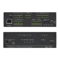
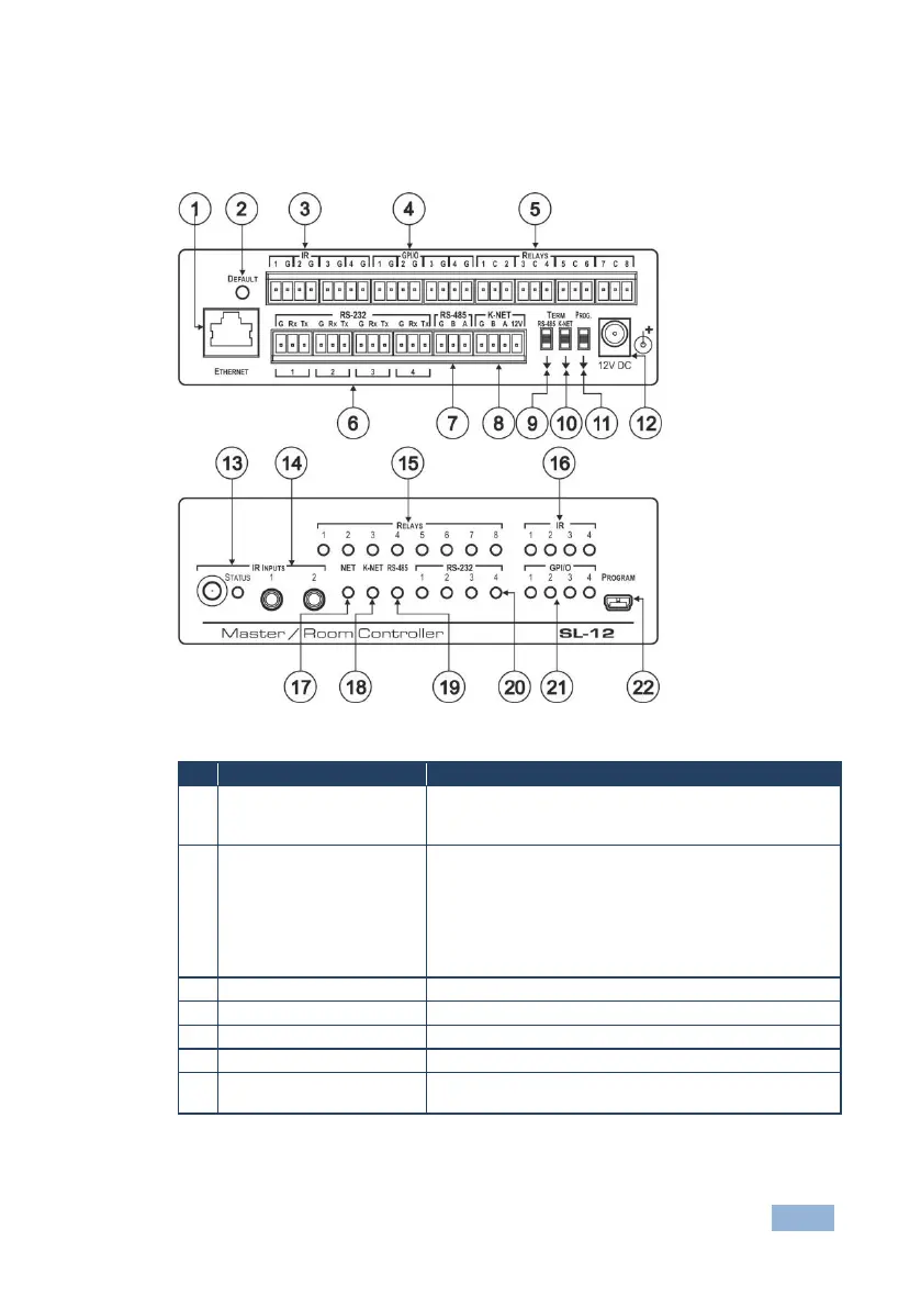
Figure 1: SL-12 Master Room Controller
Connects to the PC or other serial controller through
computer networking LAN to control several AV products
over Ethernet
DEFAULT Recessed
Pushbutton
Press to reset to factory default definitions:
IP number 192.168.1.39, Mask – 255.255.0.0,
Gateway – 0.0.0.0
First disconnect the power supply and then connect it again
while pressing the DEFAULT button. The unit powers up and
loads its memory with the factory default definitions and
erases all stored presets
IR Output Terminal Blocks
Connect to IR emitter cables (from 1 to 4)
Connect to various analog and digital sensors (from 1 to 4)
Connect to low-voltage relay-driven devices (from 1 to 8)
Connect to the RS-232 devices (from 1 to 4)
Pins B (-) and A (+) are for RS-485; Pin G may be
connected to the shield (if required)
 Loading...