4
1
4.0 Servicing on individual components
Chap. Component / Component unit Page
4.1 Right housing half . . . . . . . . . . . . . . . . . . . . . . . . . . . . . . . . . . . . . . . . . . . . . . . . . . . . .4-2
4.2 Left housing half . . . . . . . . . . . . . . . . . . . . . . . . . . . . . . . . . . . . . . . . . . . . . . . . . . . . . .4-2
4.3 Crankshaft . . . . . . . . . . . . . . . . . . . . . . . . . . . . . . . . . . . . . . . . . . . . . . . . . . . . . . . . . .4-4
4.4 Piston . . . . . . . . . . . . . . . . . . . . . . . . . . . . . . . . . . . . . . . . . . . . . . . . . . . . . . . . . . . . . .4-4
4.5 Piston ring end gap . . . . . . . . . . . . . . . . . . . . . . . . . . . . . . . . . . . . . . . . . . . . . . . . . . . .4-4
4.6 Measuring cylinder . . . . . . . . . . . . . . . . . . . . . . . . . . . . . . . . . . . . . . . . . . . . . . . . . . . .4-4
4.7 Exhaust control in cylinder . . . . . . . . . . . . . . . . . . . . . . . . . . . . . . . . . . . . . . . . . . . . . . .4-5
4.8 Preassembly of cylinder . . . . . . . . . . . . . . . . . . . . . . . . . . . . . . . . . . . . . . . . . . . . . . . . .4-5
4.9 Nikasil coating of cylinder . . . . . . . . . . . . . . . . . . . . . . . . . . . . . . . . . . . . . . . . . . . . . . .4-6
4.10 Exhaust control in clutch cover . . . . . . . . . . . . . . . . . . . . . . . . . . . . . . . . . . . . . . . . . . .4-6
4.11 Preassembly of clutch cover . . . . . . . . . . . . . . . . . . . . . . . . . . . . . . . . . . . . . . . . . . . . . .4-6
4.12 Reed valve, intake flange . . . . . . . . . . . . . . . . . . . . . . . . . . . . . . . . . . . . . . . . . . . . . . . .4-6
4.13 Kickstarter . . . . . . . . . . . . . . . . . . . . . . . . . . . . . . . . . . . . . . . . . . . . . . . . . . . . . . . . . .4-7
4.14 Preassembly of kickstarter shaft . . . . . . . . . . . . . . . . . . . . . . . . . . . . . . . . . . . . . . . . . . .4-7
4.15 Transmission . . . . . . . . . . . . . . . . . . . . . . . . . . . . . . . . . . . . . . . . . . . . . . . . . . . . . . . .4-8
4.15.1 Assembly of main shaft . . . . . . . . . . . . . . . . . . . . . . . . . . . . . . . . . . . . . . . . . . . . . . . . .4-8
4.15.2 Assembly of countershaft . . . . . . . . . . . . . . . . . . . . . . . . . . . . . . . . . . . . . . . . . . . . . . . .4-8
4.16 Clutch . . . . . . . . . . . . . . . . . . . . . . . . . . . . . . . . . . . . . . . . . . . . . . . . . . . . . . . . . . . . .4-9
4.17 Replacing outer clutch hub . . . . . . . . . . . . . . . . . . . . . . . . . . . . . . . . . . . . . . . . . . . . . . .4-9
4.18 Shift mechanism . . . . . . . . . . . . . . . . . . . . . . . . . . . . . . . . . . . . . . . . . . . . . . . . . . . . .4-10
4.19 Preassembly of shift shaft . . . . . . . . . . . . . . . . . . . . . . . . . . . . . . . . . . . . . . . . . . . . . . .4-10
4.20 Ignition (Kokusan) . . . . . . . . . . . . . . . . . . . . . . . . . . . . . . . . . . . . . . . . . . . . . . . . . . . .4-11
4.20.1 Spark plug (NGK BR 8 ECM) . . . . . . . . . . . . . . . . . . . . . . . . . . . . . . . . . . . . . . . . . . . .4-11
4.20.2 Check stator and pulse generator (Kokusan) . . . . . . . . . . . . . . . . . . . . . . . . . . . . . . . . . .4-11
4.21 Ignition (SEM) . . . . . . . . . . . . . . . . . . . . . . . . . . . . . . . . . . . . . . . . . . . . . . . . . . . . . . .4-12
4.21.1 Spark plug (NGK BR 8 ECM) . . . . . . . . . . . . . . . . . . . . . . . . . . . . . . . . . . . . . . . . . . . .4-12
4.21.2 Check stator (SEM) . . . . . . . . . . . . . . . . . . . . . . . . . . . . . . . . . . . . . . . . . . . . . . . . . . .4-12
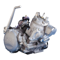
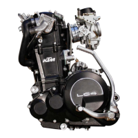
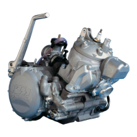
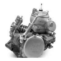
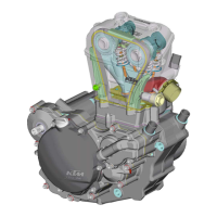
Engine housing
NOTE: READ THROUGH THE FOLLOWING SECTION BEFORE COMMENCING WORK. THEN DETERMINE THE ASSEMBLY SEQUENCE SO THAT THE ENGINE
HOUSING HALVES ONLY NEED TO BE HEATED UP ONCE BEFORE REPLACING THE BEARINGS.
H
AVING FIRST REMOVED THE DOWELS, IN ORDER TO EXPEL THE BEARINGS OR REMOVE THEM WITH LIGHT MALLET BLOWS, THE HOUSING HALVES MUST
BE PLACED ON A SUITABLY LARGE PLANE SURFACE, SUPPORTING THE WHOLE OF THE SEALING SURFACE WITHOUT DAMAGING IT. A WOODEN PANEL IS
BEST USED AS A BASE.
BEARINGS OR SHAFT SEAL RINGS SHOULD NOT BE HAMMERED INTO THEIR SEATS. IF NO SUITABLE PRESS IS AVAILABLE, USE A SUITABLE MANDREL AND
HAMMER THEM IN WITH GREAT CARE. COLD BEARINGS WILL PRACTICALLY DROP INTO THEIR SEATS AT AN ENGINE HOUSING TEMPERATURE OF APPROX.
150° C.
AFTER COOLING, SHOULD THE BEARINGS FAIL TO LOCK IN THE BORE, THEY ARE BOUND TO ROTATE AFTER WARMING. IN THAT EVENT THE HOUSING
MUST BE REPLACED.
 Loading...