If the cylinder diameter is greater than 67, 525 mm / 72,025 mm or 78,025 mm,
the Nikasil cylinder must be reconditioned or replaced.
N
OTE
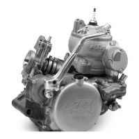
: F
OR RECONDITIONING OF THE OLD CYLINDER ALL EXHAUST CONTROL COMPONENTS
MUST BE REMOVED
. THE INTERMEDIATE FLANGE
1
REMAINS WITH THE CYLINDER.
R
ECONDITIONED CYLINDERS ARE AVAILABLE ON ORDER FROM YOUR KTM DEALER. THE PISTON
SIZE IS STAMPED INTO THE BOTTOM OF THE PISTON
.
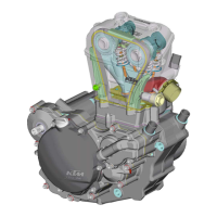
4.7 Cylinder exhaust control system
Dismantle and clean all exhaust control components, check for signs of wear and
damage.
C
ONTROL ROLLERS
2
Check clearance of bearings.
Check toothing of control rollers for signs of wear.
G
EAR SEGMENTS
3
Check toothing of gear segments and control rollers for signs of wear.
B
EARING SLEEVES
4
Check bearing sleeves of the control flap for play and easy operation.
C
ONTROL FLAP
5
Clean the control flap. The control flap must not graze inside the exhaust port.
S
ILICON O-RINGS
6
Check silicon O-rings of control flap and control rollers for signs of wear.
4.8 Cylinder preassembly
– Mount silicon O-rings
6
on control rollers and grease.
– Place control rollers
2
in cylinder and mount retaining brackets
7
; secure flat-
head screws with Loctite 242.
– Mount and grease silicon O-rings
6
on control flap and grease.
– Mount bearing sleeves
4
and gear segments
3
; mount gear segment with cylin-
der pin on right-hand side.
– Turn control rollers
2
in cylinder in such a way that ports are completely open
and no edges protrude.
– Place control flap
5
in cylinder, engage gear segments in control rollers in such
a manner that, when the control flap is ,open (pivoted right to the top), the mar-
kings
A
of the gear segments and the gear rollers coincide. Please check that the
two control rollers do not block the cross-section of the port when the control
flap is open.
– Coat sealing surface thinly with silicon and mount intermediate flange
1
with
O-rings.
– Mount exhaust flange
9
and spring hanger
bl
.
– Fix left-hand gear segment with collar screw and washer, secure screw with
Loctite 242.
– On the right-hand side, mount bearing bushing
bm
with collar outside, adjusting
lever
bn
with ball head on outside, overload spring
bo
with short leg on outside
and spring sleeve
bp
to control flap.
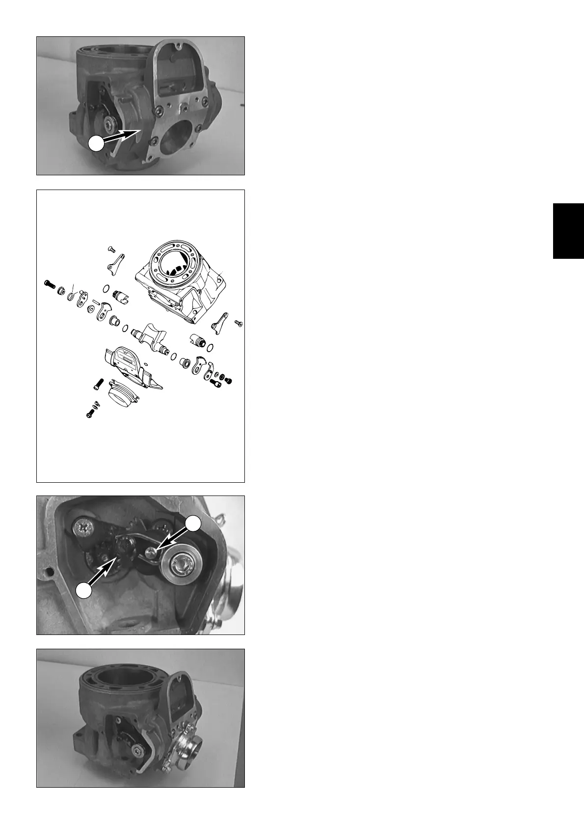
– Coat allan head screw
bq
with Loctite 242 and screw up about 5 revolutions,
hook the short leg of the overload spring on to the cylinder pin
8
(see illustra-
tion) and tighten the allan head screw.
– Finally check smooth running of exhaust control system.
N
OTE: IT MUST BE POSSIBLE TO PUSH ADJUSTING LEVER
bn
FURTHER UPWARDS AGAINST THE
SPRING FORCE
.
4
5
 Loading...