37HYDRAULIC UNIT
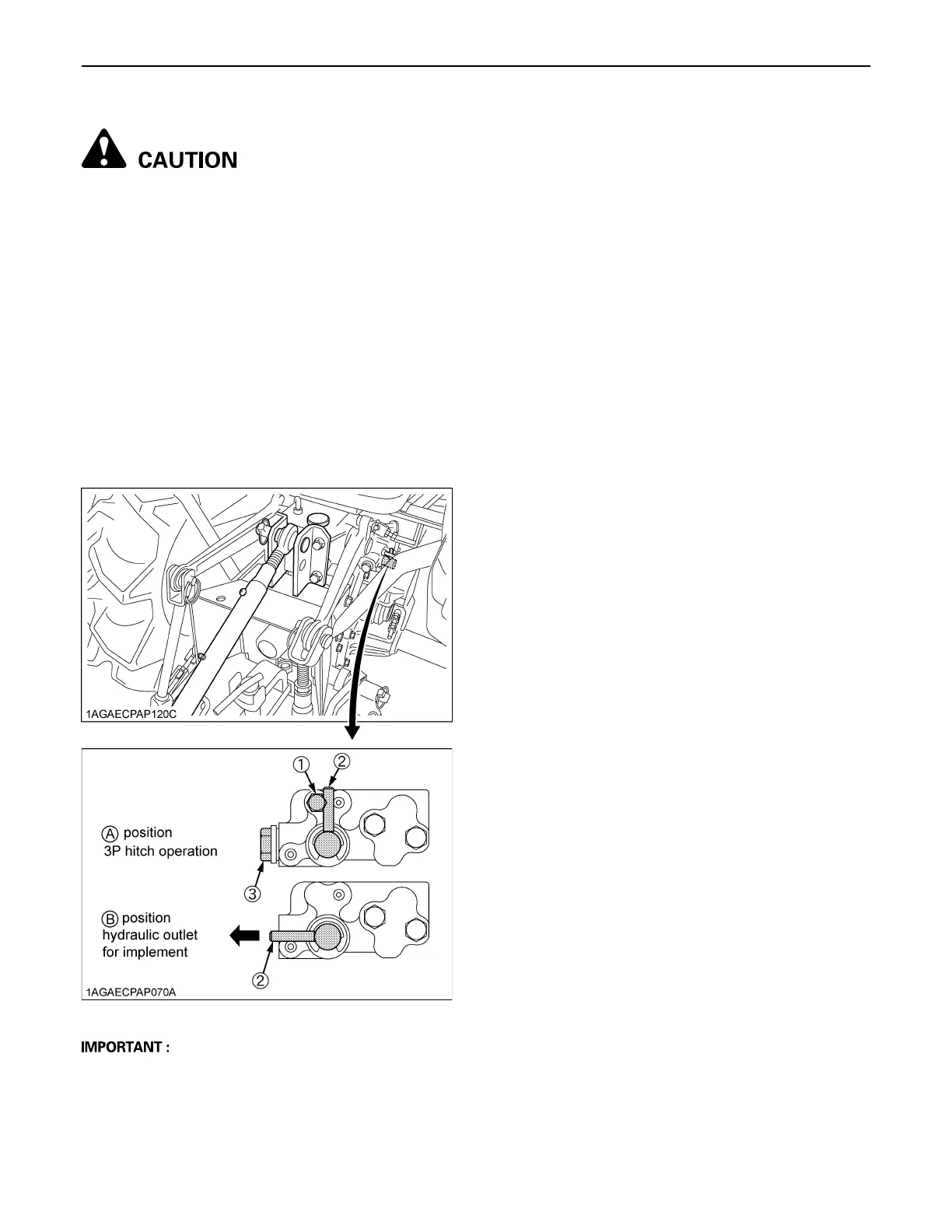
BRear outlet
To avoid personal injury:
A Stop the engine and place the hydraulic control
lever of 3-point hitch at the "neutral" position
before changing the oil flow.
When a hydraulically operated implement is connected to
the tractor, the oil flow to 3P hitch can be switched to the
cylinder on the implement by means of the lever on the
hydraulic outlet.
When implement is attached
1. Remove the plug (3) (screw: PF1/2) and restricting
bolt (1).
2. When the lever is positioned at (A), the oil flows into
the cylinder of tractor (3P hitch operation).
When the lever is turned to the position (B), the oil
flows into the cylinder on the implement.
A When implement is not attached, be sure the lever is
turned back to (A) position and restricting bolt is
installed.
A Don't place the lever at the half-way, other than (A)
and (B) positions. Or it may cause the technical
problem on the machine.
(1) Restricting bolt (2) Lever (3) Plug (PF1/2)

 Loading...