S.l
ENGINE
BODY
92.4mm
STROKE
SERIES
WSM,
01098
[3]
CYLINDER
HEAD
AND VALVES
AI 09F022
A109F023
A145F001
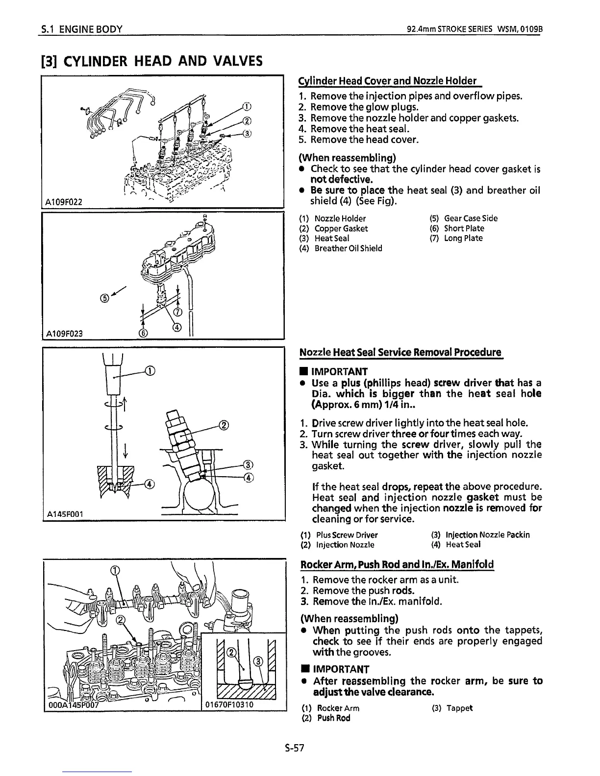
Cylinder Head Cover and Nozzle Holder
1.
Remove the injection pipes and overflow pipes.
2.
Remove the glow plugs.
3.
Remove the nozzle holder and copper gaskets.
4.
Remove the heat seal.
5.
Remove the head cover.
(When reassembling)
0
Check to
see
that
the cylinder head cover gasket
is
0
Be sure to place the heat
seal
(3)
and breather oil
(1) Nozzle Holder
(5)
Gear Case Side
(2) Copper Gasket
(6)
Short Plate
(3) HeatSeal
(7)
Long Plate
(4)
Breather
Oil
Shield
not defective.
shield
(4)
(See Fig).
Nozzle Heat Seal Service Removal Procedure
IMPORTANT
0
Use a plus (Phillips head) screw driver that has a
Dia.
which
is
bigger than the heat seal hole
(Approx.
6
mm)
114
in..
1.
Drive screw driver lightly into the heat seal hole.
2.
Turn screw driver three or four times each way.
3.
While turning the screw driver, slowly pull
the
heat
seal
out together with the injection nozzle
gasket.
If
the heat
seal
drops, repeat the above procedure.
Heat seal and injection nozzle gasket must be
changed when the injection nozzle
is
removed for
cleaning or for service.
(1)
Plus Screw Driver
(3)
Injection Nozzle Packin
(2) Injection Nozzle (4) HeatSeal
Rocker Arm, Push Rod and InJEx. Manifold
1.
Remove the rocker arm
as
a
unit.
2.
Remove the push rods.
3.
Remove the In./Ex. manifold.
(When reassembling)
0
When putting the push rods onto the tappets,
check to see
if
their ends are properly engaged
with the grooves.
I
IMPORTANT
0
After reassembling
the
rocker arm, be sure to
(1)
Rocker Arm (3) Tappet
(2)
PushRod
adjust
the
valve clearance.
s-57
 Loading...