SERVICING
LA271
•
LA301
•
LA351
•
LA401
•
LA272'
LA302'
LA352·
LA402 WSM,
17021
[3]
TIGHTENING TORQUES OF SCREWS, BOLTS AND NUTS ON THE TABLE
BELOW ARE ESPECIALLY SPECIFIED
Item
N·m
kgf.m
ft-Ibs
Control valve cover mounting bolt
23.1
to 25.7 2.4
to
2.6
17 to 19
Control valve mounting bolt
12.2 to 13.6
1.2
to
1.4
9 to 10
Connecting bar mounting bolt and nut
147
15.0
108
Control valve stay mounting bolt and nut
83
8.5
61
Front guard mounting bolt and nut
83
8.5
61
Brace mounting bolt and nut
(LA271·LA301·LA351·LA272·LA302·LA352) 135 14.0
100
(LA401·LA402)
147 15.0
108
Main frame mounting bolt (M14) 147 15.0
108
(M12)
83
8.5
61
Boom and bucket cylinder piston mounting nut
(LA271·LA301·LA351·LA272·LA302·LA352)
170 to 183
17.3
to
18.6
125 to 135
(LA401·LA402)
122 to 135
12.4 to 13.8
90 to 100
17021800020
DISMOUNTING FRONT LOADER FROM TRACTOR
• IMPORTANT
• When dismounting the loader, park the tractor on flat and hard ground, apply the parking brake.
• When starting the engine or using the hydraulic control valve, always sit
in
the operator's seat.
17000800040
[1]
LA271 • LA301 • LA351
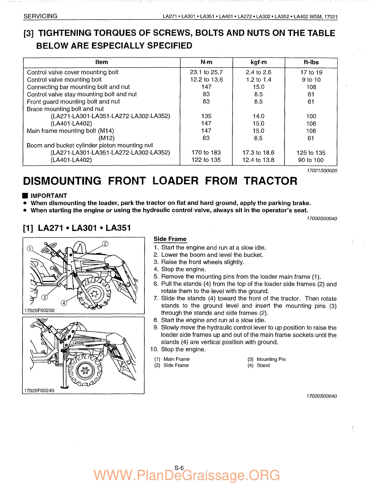
Side Frame
1.
Start the engine and
run
at a slow idle.
2.
Lower the boom and level the bucket.
3.
Raise the front wheels slightly.
4.
Stop the engine.
5.
Remove the mounting pins from the loader main frame (1).
6.
Pull the stands (4) from the top of the loader side frames
(2)
and
rotate them to the level with the ground.
7.
Slide the stands (4) toward the front of the tractor. Then rotate
stands to the ground level and insert the mounting pins
(3)
through the stands and side frames (2).
8.
Start the engine and
run
at a slow idle.
9.
Slowly move the hydraulic control lever to up position to raise the
loader side frames up and out of the main frame sockets until the
stands
(4)
are vertical position with ground.
10. Stop the engine.
17020F00230
17020F00240
(1)
Main Frame
(2)
Side Frame
S-6
(3)
Mounting Pin
(4)
Stand
17020800040
 Loading...