1-S43
ZD321, ZD326, ZD331, WSM
ENGINE
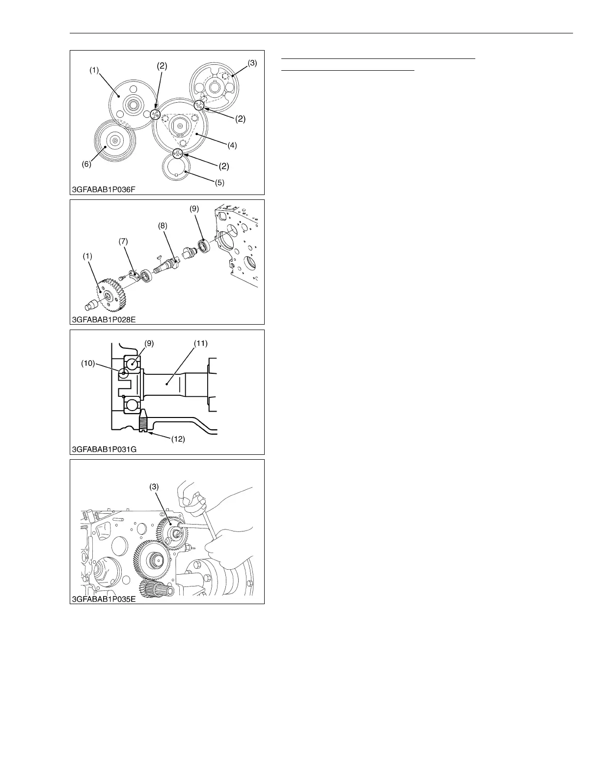
Cam Gear, Idle Gear 1 and Governor Gear
(D1005-E2-ZD, D1305-E3-ZD)
1. Remove the idle gear 1 (4).
2. Remove the fuel camshaft stopper (7).
3. Draw out the injection pump gear (1) with fuel camshaft (8).
4. Remove the camshaft stopper bolt.
5. Remove the cam gear (3) with camshaft.
6. Remove the external snap ring (10) from the governor shaft (11).
7. Remove the governor gear (6) with governor shaft (11).
• Three-lever type fork lever
To remove the governor shaft, follow the procedures in 5, 6
above and never remove fork lever and the max torque
limiter.
(When reassembling)
• Apply engine oil thinly to the fuel camshaft before installation.
• Make sure to assemble the external snap ring of the governor
shaft.
• Check the governor shaft for smooth rotation.
• When replacing the ball bearing of governor shaft, securely
fit the ball bearing (9) to the crankcase, apply an adhesive
(Three Bond 1324B or equivalent) to the set screw (12), and
fasten the screw until its tapered part contacts the
circumferential end of the ball bearing.
• When installing the idle gear, be sure to align the alignment
marks on each gears.
W1033942
(1) Injection Pump Gear
(2) Alignment Mark
(3) Cam Gear
(4) Idle Gear 1
(5) Crank Gear
(6) Governor Gear
(7) Fuel Camshaft Stopper
(8) Fuel Camshaft
(9) Ball Bearing
(10) External Snap Ring
(11) Governor Shaft
(12) Set Screw
 Loading...