2-M3
ZD321, ZD326, ZD331, WSM
TRANSAXLE
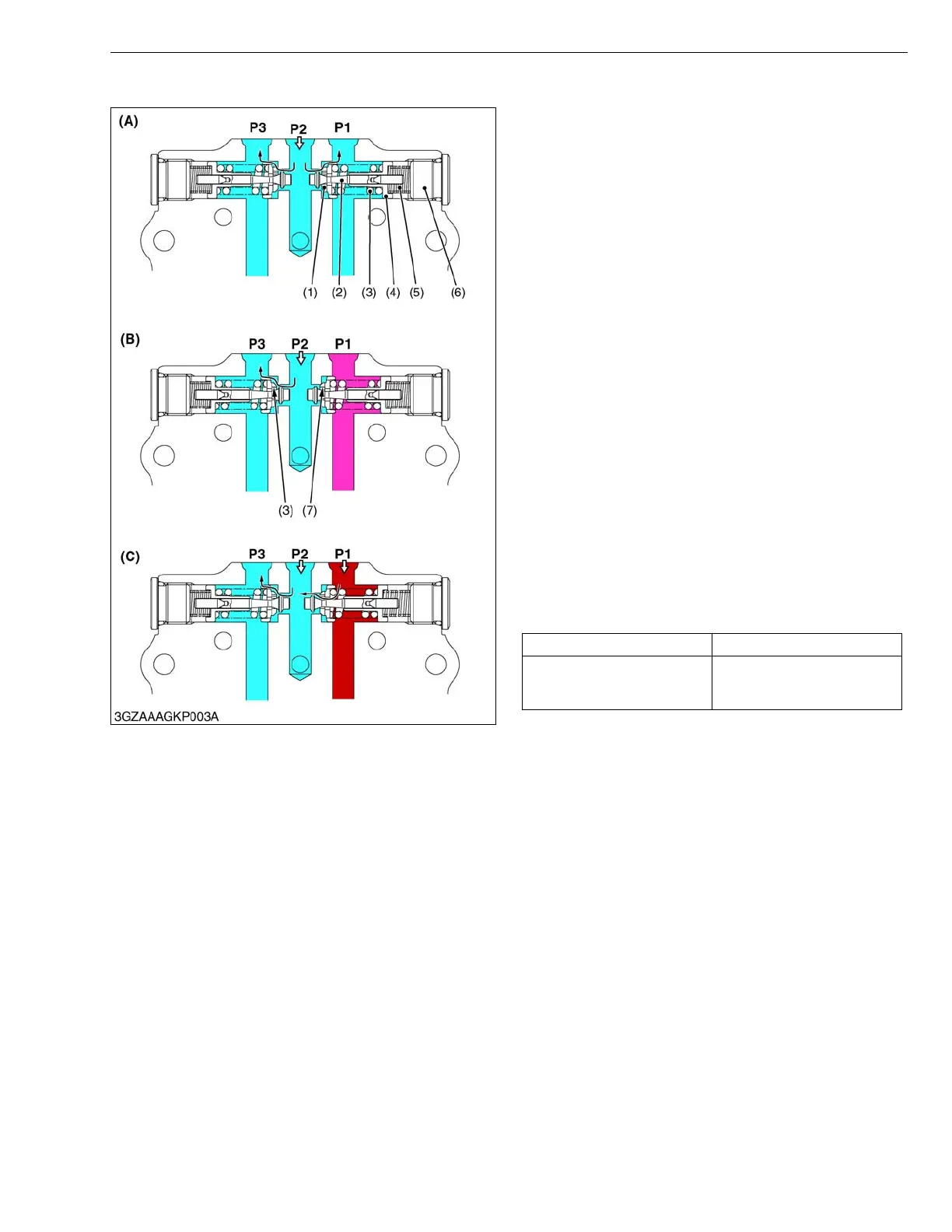
(2) Check Valve and High Pressure Relief Valve
The check and high-pressure relief valve consists of
pressure poppet (2), check valve seat (1), relief valve
spring (3), spring guide (4) and check valve spring (5).
The valve is used to prevent an overload that would
happen at a quick start, sudden stop or even during usual
running. This valve doubles as a check valve.
The check and high-pressure relief valves are laid out
facing each other as shown in the figure.
In neutral, both valves are open and charging oil
enters into the main oil circuit through the valves. (A)
At normal operation, the check valve in the high-
pressure side is closed and it pushes and opens the
another one. An excessive charge flow goes through the
charge relief valve into HST housing. (B)
The check and high-pressure relief valve along the
high-pressure line serves as a a high-pressure relief
valve. If the pressure exceeds a high-pressure limit
level, the pressure poppet opens itself against the relief
valve spring (3) force and opens the valve seat that is
located between the check valve seat (1) and the
pressure poppet (2). Now the flow goes from P1 to P2
and P3. (C)
If the P1 pressure drops, the relief valve spring forces
the valve seat closed against the pressure. The high-
pressure oil at P1 does not flow to P2 any longer.
As discussed above, the check and high-pressure
relief valve protects engines, pumps, motors, gears and
even the machine itself from overload.
Condition
• ZD321, ZD326 at engine speed 1800 min
-1
(rpm)
• ZD331 at engine speed 1600 min
-1
(rpm)
W1013226
Oil temperature Valve operating pressure
50 °C (122 °F)
19.5 to 22.5 MPa
199 to 229 kgf/cm
2
2830 to 3260 psi
(1) Check Valve Seat
(2) Pressure Poppet
(3) Relief Valve Spring
(4) Spring Guide
(5) Check Valve Spring
(6) Valve Plug
(7) Neutral Orifice
(A) In Neutral (Stop)
(B) When Check Valve
Activating (Normal
Operation)
(C) When High Pressure Relief
Valve Activating
P1 :Forward
P2 :Change
P3 :Reverse
 Loading...