4-M5
ZD321, ZD326, ZD331, WSM
HYDRAULIC SYSTEM
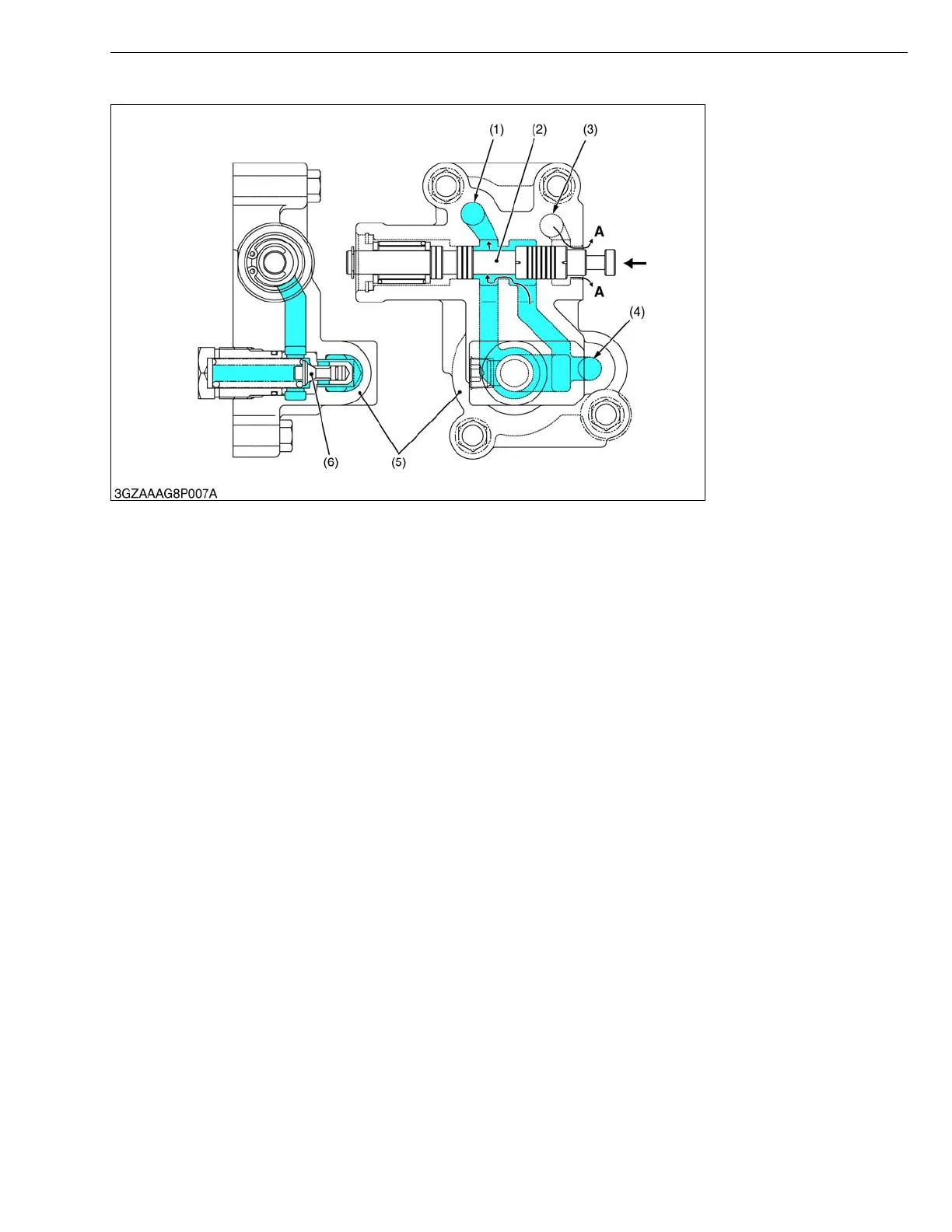
■ Down
W1013905
The oil sent from the pump passes through a gap between the spool (2) and the valve body (5), through the
regulator valve, and then the oil flows to the PTO valve and HST charge circuit.
The mower-lifting cylinder circuit, which has been interrupted by the spool, is returned to the transmission center
case by the pressed-in spool, and a new circuit if formed.
Then the oil in the mower-lifting cylinder is discharged to the transmission center case, and the mower goes down.
(1) To PTO Clutch and
Hydrostatic Transmission
(2) Spool
(3) C (Cylinder) Port
(4) P (Pump) Port
(5) Valve Body
(6) Relief Valve
A : Drain directly to the
Transmission Center Case
 Loading...