2PG/2PH
2-2-1
2-2 Electrical Parts Layout
2-2-1 Electrical parts layout
(1) PWBs
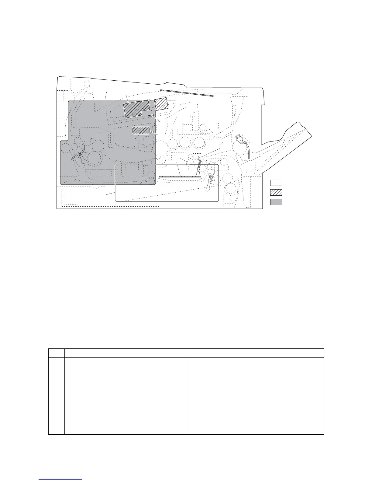
Figure 2-2-1 PWBs
1. Control PWB ................................................ Main controller: Controls the software such as the print data processing
and provides the interface with computers.
Engine: Controls printer hardware such as high voltage/bias output con-
trol, paper conveying system control, and fuser temperature control, etc.
2. Power source PWB...................................... After full-wave rectification of AC power source input, switching for
converting to 24 V DC for output. Controls the fuser heater lamp.
3. High voltage PWB........................................ Generates main charging, developing bias and transfer bias.
4. Operation panel PWB .................................. Consists the LED indicators and key switches.
5. APC PWB .................................................... Generates and controls the laser beam.
6. PD PWB....................................................... Controls horizontal synchronizing timing of laser beam.
7. Zener PWB .................................................. Adjusts the drum surface potential.
8. Eraser lamp PWB ........................................ Eliminates the residual electrostatic charge on the drum.
List of correspondences of PWB names
No. Name used in service manual Name used in parts list
1 Control PWB P.W.BOARD ASSY CONTROL WITH SOFTWARE(SP)
2 Power source PWB SWITCHING REGULATOR 120V
SWITCHING REGULATOR 230V
3 High voltage PWB HIGH VOLTAGE UNIT
4 Operation panel PWB P.W.B BOARD ASSY PANEL
5 APC PWB -
6PD PWB -
7 Zener PWB -
8 Eraser lamp PWB -
 Loading...