LAUNCH Injector Cleaner & Tester User’s Manual
20
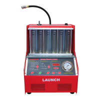
Appendix 2: Electrical Diagram
8
4
T2
T1
T4
T3
M
6
5
7
GND
L
N
J5
J1
T6
T5
J4
J11
2
J2
J3
JA
3
L
GND
N
1-Pump; 2-Drive board; 3-Control panel; 4-Level switch; 5-Solenoid valve; 6-Injector; 7-Switching type
power supply;8-Backlight; 9-Power switch; 10-Fuse; 11-Socket for power supply; 12-Operating panel.
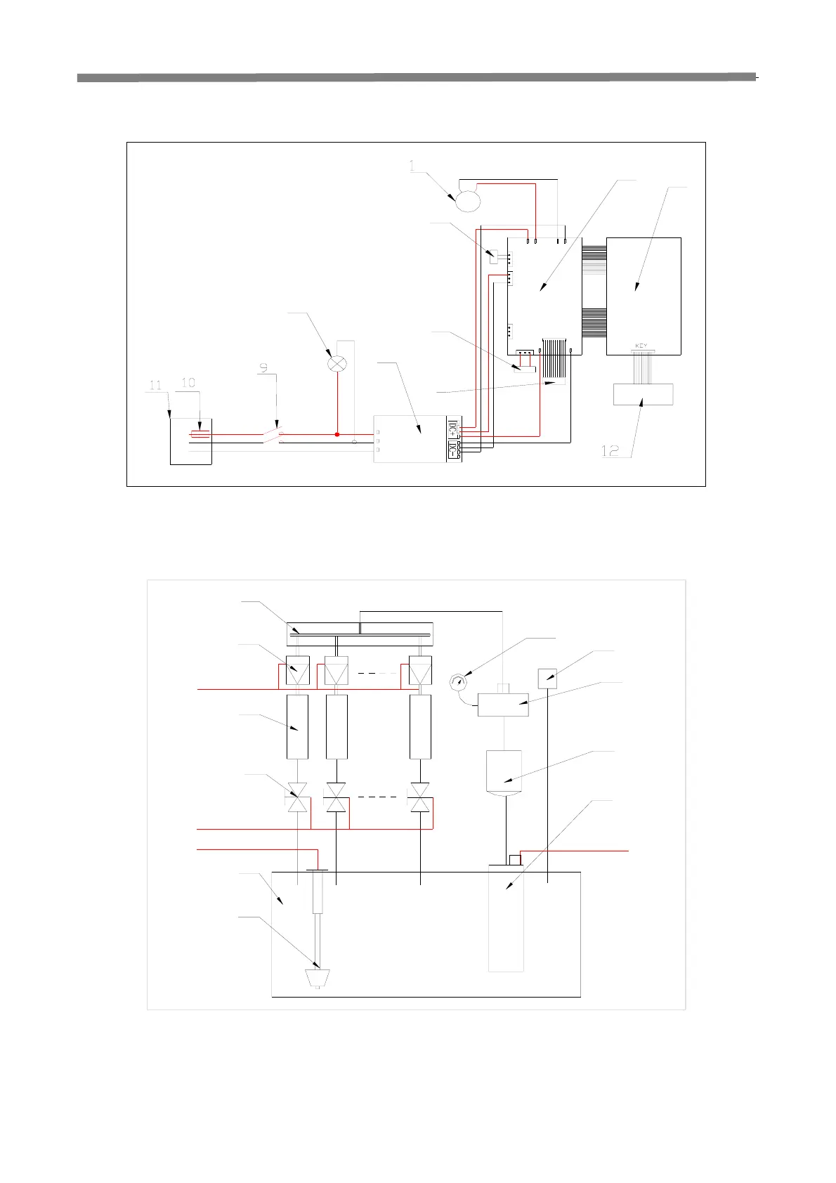
Appendix 3: Fuel Path Diagram
11
10
D
8
7
9
A
2
1
3
4
B
C
6
5
1-Fuel distributor; 2-Injector; 3-Mesuring tube; 4-Solenoid valve; 5-Fuel tank; 6-Level switch; 7-Fuel pump; 8-Filter; 9-return
hose connector; 10- Tee joint; 11-Pressure gauge; A-Injector pulse signal cables;B-Control cables for solenoid valve;
C-Control cables for level switch; D-Power control cables for fuel pump.
 Loading...