LAUNCH CNC-603A Injector Cleaner & Tester User Manual
3
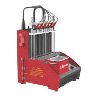
II. Structure of CNC-603A Injector Cleaner & Tester
2.1 Structure
The schematic diagram of CNC-603A Injector Cleaner & Tester is shown in Figure 2.1:
Attention: there may be slight difference between the illustrations in this manual and the actual product.
The actual product prevails.
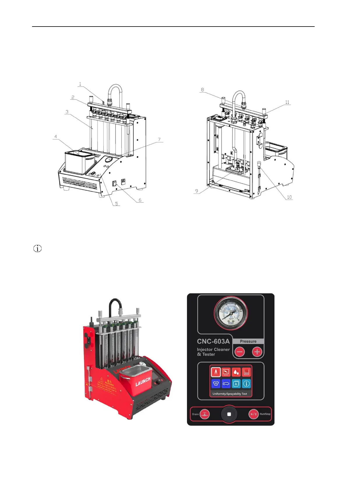
2.2 Control Panel
The control panel is shown in Figure 2.2:
Figure 2.2 Diagram of control panel
1- Pulse line; 2-Fuel distributor assembly; 3-Observation window tube; 4-Ultrasonic cleaner;
5-Control panel; 6-Power switch; 7-Fuel pressure gauge; 8-Quick Connector ; 9-Fuel pump;
10-Fuel drainage pipe; 11-Automatic cleaning oil return port
 Loading...