12
LAUNCH
Professional 129E User Manual
5. Diagnose
5.1 Connection
1. Turn the ignition off.
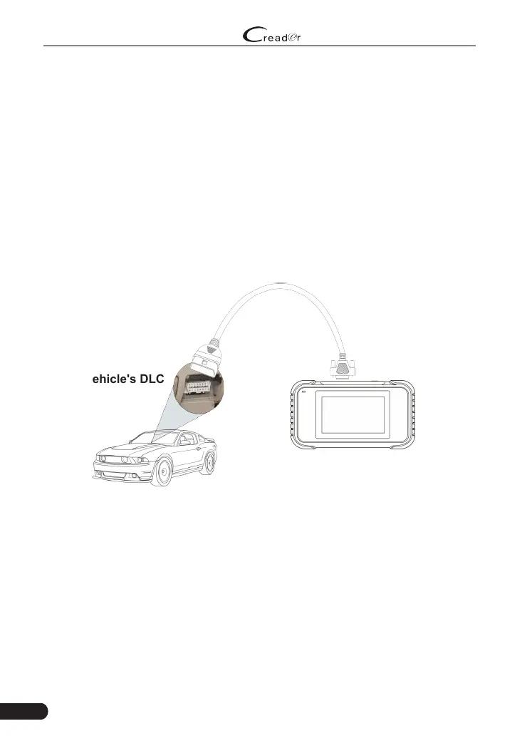
2. Locate vehicle’s DLC socket: It provides standard 16 pins and is generally
located on driver’s side, about 12 inches away from the center of dashboard.
See Figure 2-2. If DLC is not equipped under dashboard, a label indicating
its position will be given. In case no DLC is found, please refer to Automobile
Repair Manual.
3. Plug one end of the diagnostic cable into the DB-15 connector of the tool, and
tighten the captive screws. Connect the other end to the vehicle’s DLC.
Diagnostic Cable
Creader Professional 129E
Vehicle's DLC
Figure 5-1
5.2 System Diagnosing
This function is specially designed to diagnose electronic control systems of
single vehicle model.
5.2.1 Smart Diagnosis (Auto-Detect)
After connection, turn the ignition key on and the system enters auto-detect
mode (
*Note: Please make sure the “Automac detecon on connect” in “Sengs” is
set as ON
).
 Loading...