2
Common application – Classroom: Position the sensor so that the maximum
coverage is achievable. Be sure that the sensor is not pointing out the door. To get
complete coverage in an open office area, install multiple sensors so that there is
approximately 20% overlap with each adjacent sensor’s ultrasonic coverage area.
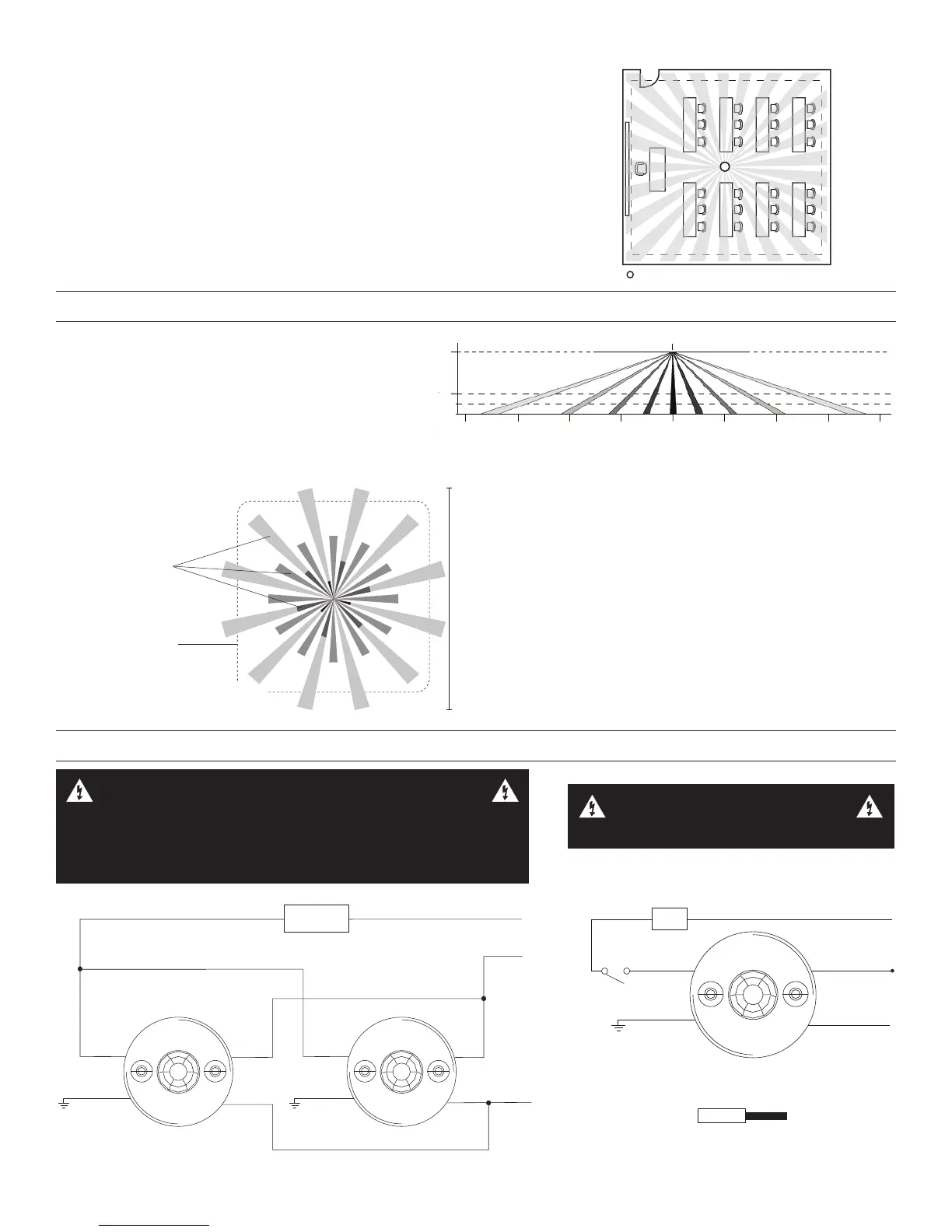
COVERAGE PATTERN
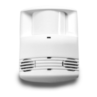
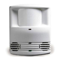
The DT-355 provides a 360° coverage pattern. The
coverage shown represents walking motion at a mounting
height of 8-12 feet. For building spaces with lower levels
of activity or with obstacles and barriers, coverage size
may decrease. The coverage for PIR ONLY trigger mode
varies with mount height. Refer to pattern below for details.
Ultrasonic coverage is roughly the same for 8-12 foot
mount heights. Refer to PIR and Ultrasonic trigger mode
coverage for details.
8ft
(2.4m)
10ft
(3.0m)
12ft
(3.7m)
40ft
(12.2m)
30ft
(9.1m)
40ft
(12.2m)
30ft
(9.1m)
20ft
(6.1m)
20ft
(6.1m)
10ft
(3.0m)
10ft
(3.0m)
0
0
PIR Only Coverage
Side View
36 ft
(10.97m)
36 ft x 36 ft
PIR
Coverage
Ultrasonic
Coverage
Top View
8-12 foot Mounting Height
* Drawings not to scale, representative of PIR
and Ultrasonic Trigger Mode major motion
coverage
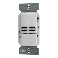
WIRING DIRECTIONS
Strip Gauge
#12 to #16 AWG
Cu Wire Only
Single Sensor, Single Load
Load
Load Hot
Neutral
Ground
(Optional)
NOTE: This application does not allow for Load to increase
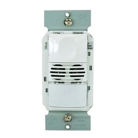
Multiple Sensors Connected in Parallel
Hot
Neutral
Load
Load
Load
Line
Neutral
Line
Ground
(Optional)
Ground
(Optional)
WARNING: DO NOT INSTALL THE SENSOR IN A SPACE
CONTROLLING A TOTAL LOAD THAT IS HIGHER THAN THE RATING
OF THE DEVICE. EACH SENSOR WILL NEED TO SWITCH THE ENTIRE
LOAD EVEN IF ADDITIONAL SENSORS ARE INSTALLED. RISK OF
OVERLOAD, PRODUCT DAMAGE, SMOKE AND/OR FIRE MAY RESULT.
WARNING: TURN THE POWER
OFF AT THE CIRCUIT BREAKER
BEFORE INSTALLING SENSORS.
 Loading...