Page 7
control And sensor connection requirements
The following are sensor connections and wiring require-
ments for the discharge air and outdoor air sensors.
dischArge sensor (dAt)
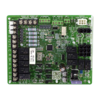
The air handler control has two screw terminals marked
Discharge Air Sensor. The sensor is REQUIRED for
EVENHEAT operation and is eld mounted and ordered
separately using Lennox Catalog # 88K38.
outdoor Air sensor (oAs)
This is a two screw terminal for connection to a Lennox
X2658 outdoor temperature sensor.
indoor Blower signAl 6-pin connector (p7)
This is the connection between the air handler control and
the B3 Indoor Blower Motor.
Table 1. . Indoor Blower Signal (P7)
Position Function / Description
1 TX
2 C
3 Not used
4 RX
5 +V
6 Not used
Air hAndler control 9-pin connector (p8)
1. Air Handler (no electric heat) – Two wire factory harness
(wired to pins 7 and 8) which provides 230 VAC power
to air handler control.
2. Air Handler (with electric heat) – Eight wire factory
harness (all pin position are wired as noted in table 2).
NOTE – See gure 4, Detail B for wire colors.
Table 2. . Electric Heat Connection (P8)
Position Function / Description
1 Heat stage 1 relay coil
2 Heat stage 2 relay coil
3 Relay coil return
4 Heat stage 3 relay coil
5 Heat stage 4 relay coil
6 Heat stage 5 relay coil
7 L1 230VAC supply from heater kit
8 L2 230VAC supply from heater kit
9 Not used
This section provides information on communicating and
non-communicating control connections and wire run
lengths.
Table 3. . Air Handler Control Connections –
Communicating
Item Label Function
Thermostat
R 24VAC
i+ RSbus data high connection
i- RSbus data low connection
C 24VAC command (ground)
Outdoor Unit
R 24VAC
i+ RSbus data high connection
i- RSbus data low connection
C 24VAC command (ground)
Table 4. . Air Handler Control Connections –
Non-Communicating
Label Function
W1 First-stage heating demand
W2 Second-stage heating demand. W1 input
must be active to recognize second stage
heat demand.
W3 Third-stage heating demand. W1 and W2 in-
puts must be active to recognize third stage
heat demand.
G Indoor blower demand
Y1 and
Y2
First- and second-stage cooling demands
C 24VAC common
R 24VAC power
DH 24VAC output for dehumidication for com-
municating systems.
H 24VAC output for humidication
O Reversing valve demand. (Energized by
thermostat in cooling mode.)
DS Blower speed control input for non-com-
municating Harmony zoning or thermostat
dehumidication control.
WARNING
Electric Shock Hazard. Can cause injury or
death. Unit must be properly grounded in
accordance with national and local codes.
Line voltage is present at all components
when unit is not in operation on units with
single-pole contactors. Disconnect all remote
electric power supplies before opening
access panel. Unit may have multiple power
supplies.
 Loading...