Page 6
(VALVE STEM SHOWN
CLOSED) INSERT HEX
WRENCH HERE
SERVICE PORT CORE
SERVICE PORT CAP
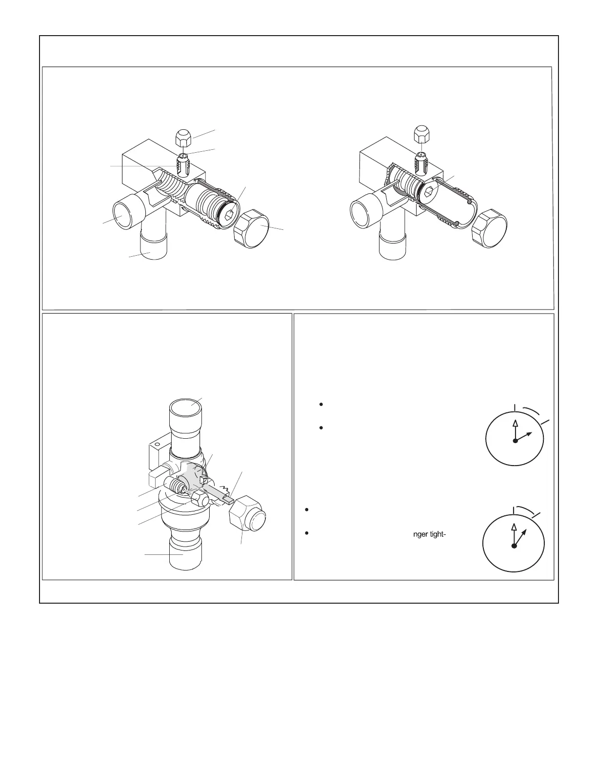
ANGLE-TYPE SERVICE VALVE
(FRONT-SEATED CLOSED)
SERVICE PORT
CORE
TO OUTDOOR UNIT
STEM CAP
(VALVE STEM SHOWN OPEN)
INSERT HEX WRENCH HERE
TO INDOOR
UNIT
ANGLE-TYPE SERVICE VALVE
(BACK-SEATED OPENED)
BALL (SHOWN
CLOSED)
SERVICE PORT
CORE
TO INDOOR UNIT
TO OUTDOOR
UNIT
TO OPEN ROTATE STEM
COUNTERCLOCKWISE 90°.
TO CLOSE ROTATE STEM
CLOCKWISE 90°.
SERVICE PORT
SERVICE PORT
CAP
STEM CAP
VALVE
STEM
ANGLE AND BALL
Operating Angle Type Service Valve:
1. Remove stem cap with an appropriately sized wrench.
2. Use a service wrench with a hex-head extension (3/16” for liquid line valve sizes and 5/16” for vapor line valve sizes) to back
the stem out counterclockwise as far as it will go.
Operating Ball Type Service Valve:
1. Remove stem cap with an appropriately sized wrench.
2. Use an appropriately sized wrenched to open. To open valve,
roate stem counterclockwise 90°. To close rotate stem clockwise
90°.
1
2
3
4
5
6
7
8
9
10
11
12
1/12 TURN
To Access Service Port:
A service port cap protects the service port core from contamination and
serves as the primary leak seal.
1. Remove service port cap with an appropriately sized wrench.
2. Connect gauge set to service port.
3. When testing is completed, replace service port cap and tighten as
follows:
With torque wrench: Finger tighten and
torque cap per table 3.
Without torque wrench: Finger tighten and
use an appropriately sized wrench to turn
an additional 1/6 turn clockwise.
1
2
3
4
5
6
7
8
9
10
11
12
1/6 TURN
WHEN SERVICE VALVE IS CLOSED, THE SERVICE PORT IS OPEN
TO
THE LINE SET AND INDOOR UNIT.
When service valve is OPEN, the service port is
open to linE set, indoor and outdoor unit.
Reinstall Stem Cap:
Stem cap protects the valve stem from damage and serves as the
primary seal. Replace the stem cap and tighten as follows:
With Torque Wrench: Finger tighten and
then torque cap per table 3.
Without Torque Wrench: Fi
en and use an appropriately sized
wrench to turn an additional 1/12 turn
clockwise.
NOTE — A label with specific torque requirements may be affixed to the stem cap. If the label is present, use the specified torque.
FIGURE 2. Angle and Ball Service Valves
 Loading...