Page 19
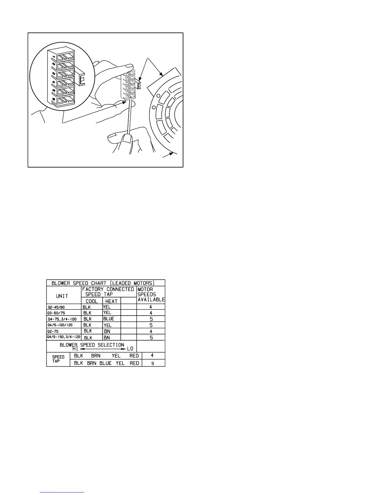
FIGURE 24
BLOWER SPEED TAP SELEC-
TION
Leaded Motors
HARNESS
CONNECTOR
MOTOR
DEPRESS TAB TO RELEASE
WIRE TERMINAL. SELECT
CONNECTOR LOCATION
FOR NEW SPEED (REFER TO
UNIT WIRING DIAGRAM). IN-
SERT WIRE UNTIL IT IS SE-
CURELY IN PLACE.
E−Blower Speed Taps Leaded Motors
80UHG−2 Models
Blower speed tap changes are made on the SureLight
control board. See figure 6. Unused taps must be secured
on two dummy terminals labeled "PARK on the SureLight
board. The heating tap is connected to the "HEAT−H " ter-
minal and the cooling tap is connected to the "COOL−H"
terminal. The continuous blower tap is the same as the
heating tap.
To change existing heat tap, turn off power then switch out
speed tap on "HEAT−H" with tap connected to "PARK" .
See table 12 for blower motor tap colors for each speed.
TABLE 12
VI−MAINTENANCE
At the beginning of each heating season, the system
should be checked as follows:
A−Filters
Return air filter is not supplied with unit. See Optional Ac-
cessaries section in this manual for filter and rack size. A
filter must be used in order to ensure long life and proper
operation. The filter is located in the return air duct or return
air register. Filters must be cleaned or replaced when dirty
to assure proper unit operation.
B− Heat Exchanger and Burners
Due to dimples designed in the heat exchanger, cleaning
is not recommended. Removal is for inspection only.
NOTE−Use papers or protective covering in front of fur-
nace while cleaning furnace.
To clean burners:
1 − Remove screws holding upper burner mounting rail (fig-
ure 17). Remove rail.
2 − Slide burners off each orifice pull burners from heat ex-
changer.
3 − Clean holes in burner head (retention ring) with a wire
brush. See figure 17.
4 − With a shop vacuum or rags, clean out soot and scale
deposits from burners.
5 − Remove screws securing flue box to vestibule panel.
Remove flue box from unit. Leave combustion air
blower attached to flue box.
6 − With a shop vacuum or rags, clean out soot and scale
deposits from heat exchanger tubes and flue box. If tur-
bulators are removed (figure 1) make sure they are re-
installed before reassembling units.
7 − Inspect heat exchanger for corrosion damage, holes or
cracks.
8 − Replace burners making sure to fully engage on orifice.
Resecure burner mounting rail and flue box. Inspect flue
box gasket. Replace gasket if necessary.
9 − Slide heat exchanger into cabinet and re-secure heat
exchanger screws.
10 − Reinstall filler piece making sure that there is a good
seal between the cabinet sides, blower and deck and
filler piece. Use silicon caulking to fill in any potential
gaps.
11 − Re-secure flue pipe, gas piping and access panels.
12 − Carefully check all piping connections (factory and
field) for gas leaks. Use a leak detecting solution or oth-
er preferred means.
12 − Turn on gas and electrical supply.
 Loading...


