Page 15
Air Flow – Cooling Blower Speed
The cooling blower speed is factory congured to provide
correct air ow for an outdoor unit that matches the cool-
ing capacity rating of the air handler.
If the outdoor unit is smaller than the maximum cooling ca-
pacity rating for the air handler, the cooling blower speed
may need to be changed. Refer to blower performance
chart, table 2 on page 16 .
WARNING
Electric shock hazard! - Disconnect all power
supplies before servicing.
Replace all parts and panels before
operating.
Failure to do so can result in death or
electrical shock.
CHANGE BLOWER SPEED
1 - Disconnect all power supplies.
2 - Remove the air handler access panel.
3 - Locate pin number 2 on the blower relay. Two
black wires are connected to this terminal pin. One
connects to pin number 5 on the blower relay, one
connects to an in-line splice connecting to a blue
wire.
4 - Select the required blower motor speed. Connect
red-LO or black-HI and plug it into the 4-pin blower
relay harness connector.
NOTE - Reuse the factory-installed wire nut on the un-
used wires.
5 - Replace all panels.
6 - Reconnect power.
R
G
AIR
CONDITIONER
UNIT
R
R
G
G
BU
W
W
BK
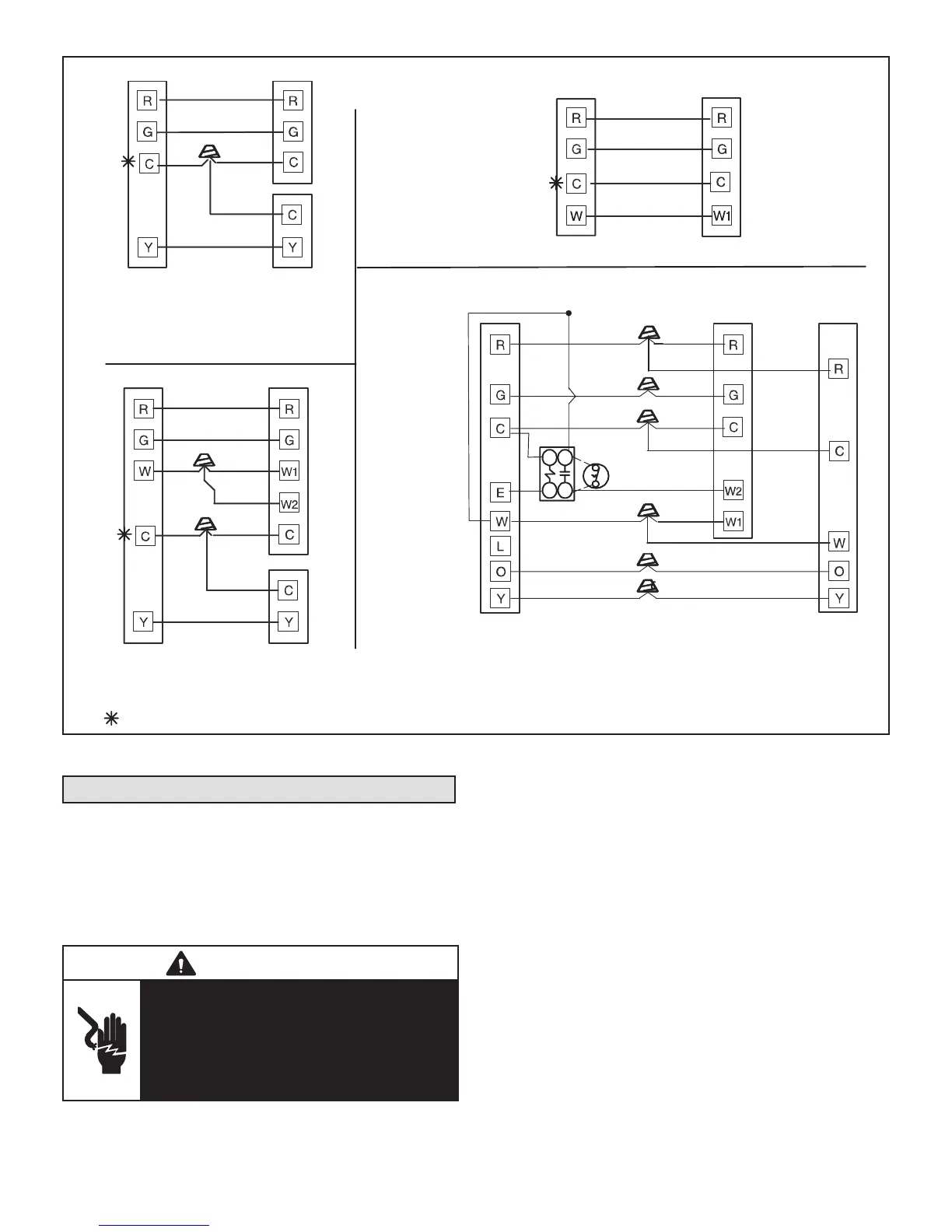
COOLING‐ONLY APPLICATION
HEAT‐ONLY APPLICATION
AIR HANDLERTHERMOSTAT
COOLING APPLICATION WITH
ELECTRIC HEAT
AIR HANDLERTHERMOSTAT
HEAT PUMP APPLICATION WITH
ELECTRIC HEAT
NOTE - Connect common wire only if required (Refer to the appropriate thermostat installation instructions).
BU
BU
SEE
NOTE
SEE
NOTE
SEE
NOTE
Y
Y
AIR CONDITIONER
UNIT
R
G
BU
W
BK
CONNECT COMMON
WIRE ONLY IF
REQUIRED
(REFER TO THE
APPROPRIATE
THERMOSTAT
INSTALLATION
INSTRUCTIONS)
AIR HANDLER
THERMOSTAT
HEAT PUMP
UNIT
FIGURE 15. Low Voltage Connections (3-Speed PSC Motor) – Field Wiring

 Loading...