Page 17
• Is the wiring neat, correct, and in accordance with the
wiring diagram?
• Is the unit properly grounded and protected (fused)?
• Is the thermostat correctly wired and in a good location?
• Are all access panels in place and secure?
CHECK BLOWER OPERATION
• Set thermostat to FAN ON.
• The indoor blower should come on.
CHECK COOLING OPERATION
• Set thermostat to force a call for cooling (approximately
5ºF lower than the indoor ambient temperature).
• The outdoor unit should come on immediately and the
indoor blower should start between 30 - 60 seconds lat-
er.
• Check the air ow from a register to conrm that the
system is moving cooled air.
• Set the thermostat 5ºF higher than the indoor tempera-
ture. The indoor blower and outdoor unit should cycle
off.
CHECK ELECTRIC HEAT (IF USED)
• Set thermostat to call for auxiliary heat (approximate-
ly 5°F above ambient temperature). The indoor blow-
er and auxiliary heat should come on together. Allow a
minimum of 3 minutes for all sequencers to cycle on.
• Set the thermostat so that it does not call for heat. Allow
up to 5 minutes for all sequencers to cycle off.
Operation
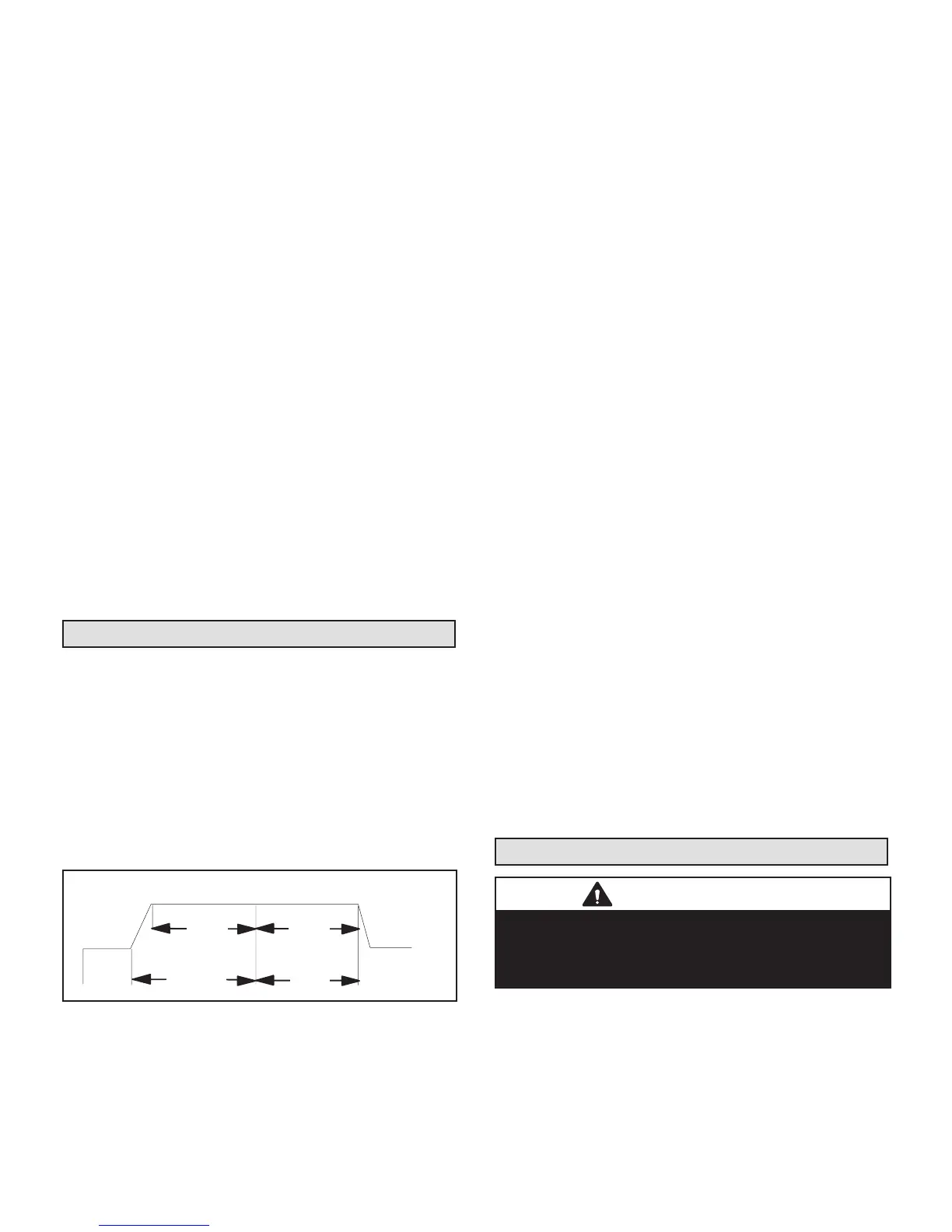
TIME DELAY RELAY
Blower time delay operation:
1 - When cooling demand is initiated, there is a 1
second motor-on delay.
2 - After the motor-on delay expires, motor ramps up
to 100% and runs at 100% until cooling demand is
satised.
3 - Once demand is met, motor runs at 100% for 45
seconds.
4 - Motor ramps down to stop.
1
SECOND
DELAY
OFF
100%
CFM
100%
CFM
45
COOLING
DEMAND
1
2
FIGURE 17. Blower Time Delay
COOLING (COOLING ONLY OR HEAT PUMP)
When the thermostat calls for cooling, 24 volts is put on
the blower time-delay relay coil and then the indoor blow-
er relay energizes. The normally open contacts close,
causing the indoor blower motor to operate. The circuit
between R and Y is completed, closing the circuit to the
contactor in the outdoor unit, starting the compressor and
outdoor fan motor.
On heat pumps, circuit R and O energizes the reversing
valve, switching the valve to the cooling position. (The re-
versing valve remains energized as long as the thermo-
stat selector switch is in the COOL position.)
At the completion of the cooling demand the indoor blower
and outdoor unit should cycle off. Air handler should cycle
off 45 seconds after the outdoor unit shuts off.
HEATING (ELECTRIC HEAT ONLY)
When the thermostat calls for heat, the circuit between R
and W is completed, and the heat sequencer is energized.
A time delay follows before the heating elements and the
indoor blower motor come on. Units with a second heat
sequencer can be connected with the rst sequencer to W
on the thermostat sub-base, or they may also be connect-
ed to a second stage on the sub-base.
HEATING (HEAT PUMP)
When the thermostat calls for heating, 24 volts is applied
to the blower time-delay relay coil. Then, normally open
contacts close, causing the indoor blower motor to oper-
ate. The circuit between R and Y is completed, closing
the circuit to the contactor in the outdoor unit, starting the
compressor and outdoor fan motor.
If the room temperature continues to decrease, the cir-
cuit between R and W1 is completed by the second-stage
heat room thermostat. Circuit R-W1 energizes a heat se-
quencer. The completed circuit will energize supplemen-
tal electric heat (if applicable). Units with a second heat
sequencer can be connected with the rst sequencer to
W1 on the thermostat. They may also be connected to
a second heating stage W2 on the thermostat sub-base.
EMERGENCY HEAT (HEATING HEAT PUMP)
If the selector switch on the thermostat is set to the emer-
gency heat position, the heat pump will be locked out of
the heating circuit, and all heating will be electric heat (if
applicable). A jumper should be placed between W2 and E
on the thermostat sub-base so that the electric heat con-
trol will transfer to the rst-stage heat on the thermostat.
This will allow the indoor blower to cycle on and off with
the electric heat when the fan switch is in the AUTO po-
sition.
Homeowner Maintenance
IMPORTANT
Do not operate system without a lter. A lter is required
to protect the coil, blower, and internal parts from
excessive dirt and dust. The lter is placed in the return
duct by the installer.
• Inspect air lters at least once a month and replace or
clean as required. Dirty lters are the most common
cause of inadequate heating or cooling performance.
• Replace disposable lters. Cleanable lters can be
cleaned by soaking in mild detergent and rinsing with
cold water.

 Loading...