Page 8
NOTE - Check local codes before connecting the drain
line to an existing drainage system. Insulate the drain
lines where sweating could cause water damage.
TEST CONDENSATE DRAIN
Test the drain pan and drain line after installation:
1 - Pour several quarts of water into drain pan. Use
enough water to ll both the drain trap and the line.
2 - Check the installed drain pan. Drain pan must be
draining completely. Drain line ttings must not be
leaking. Water must be draining from the end of the
primary drain line.
3 - Correct any leaks found.
Duct System and Filters
DUCT SYSTEM
The air handler is provided with anges for the connection
of the supply plenum.
Supply and return duct system must be adequately sized
to meet the system’s air requirements and static pressure
capabilities. The duct system should be insulated with a
minimum of 1" thick insulation with a vapor barrier in con-
ditioned areas or 2" minimum in unconditioned areas.
Supply plenum should be the same size as the anged
opening provided around the blower outlet and should ex-
tend at least 3 ft. from the air handler before turning or
branching off plenum into duct runs. The plenum forms an
extension of the blower housing and minimizes air expan-
sion losses from the blower.
FILTERS
A lter is provided. Table 1 lists the lter size for each unit.
TABLE 1. Unit Air Filter Size Chart
CBA25UH Filter Size – In.
-018, -024, -030 15" x 20" x 1"
-036, -042, -048, -060 18" x 20" x 1"
IMPORTANT
If a high efciency lter is being installed as part of this
system to ensure better indoor air quality, the lter must
be properly sized. High efciency lters have a higher
static pressure drop than standard efciency glass/foam
lters. If the pressure drop is too great, system capacity
and performance may be reduced. The pressure drop
may also cause the limit to trip more frequently during
the winter and the indoor coil to freeze in the summer,
resulting in an increase in the number of service
calls. Before using any lter with this system, check
the specications provided by the lter manufacturer
against the data given in the appropriate Lennox Product
Specications bulletin. Additional information is provided
in Service and Application Note ACC002 (August 2000)..
INSTALL CONDENSATE DRAIN
The air handler is provided with 3/4" NPT condensate
drain connections.
IMPORTANT
On some pans, the primary and secondary drain holes
have knockouts.
Conrm primary and secondary drains are open.
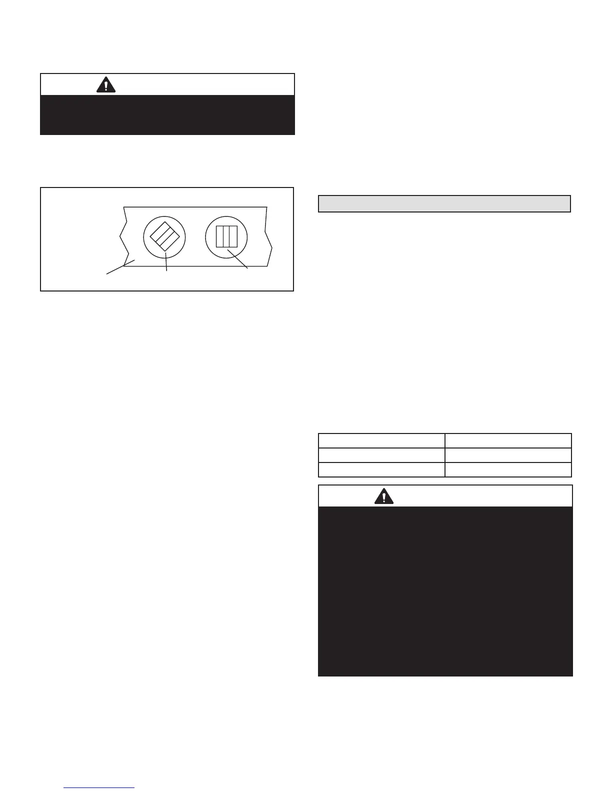
1 - CBA25UH units are equipped with a drain pan, which
includes green (main drain) and red (secondary
drain) plugs. Unscrew the plugs to remove them
before inserting condensate drain ttings.
DRAIN PAN
RED SECONDARY
UNSCREW PLUGS
AND CONNECT
PROPERLY SIZED
FIELD-PROVIDED
FITTINGS AND
DRAIN LINES.
GREEN MAIN
FIGURE 8. Drain Line Connections
2 - Install properly sized, eld-provided connection
ttings and connect primary drain line to the main
drain pan connection.
NOTE - When installing drain line connection ttings to
the drain pan, hand tighten the tting and use a thread
sealant. Over-tightening the ttings can split connections
on the drain pan.
3 - If the secondary drain line is to be used, remove the
plug or the knockout and route the drain line so that
water draining from the outlet will be easily noticed
by the homeowner. Refer to local codes for drain
trap requirements on the secondary drain line.
4 - Check again to ensure drain ports and drain pan
are free of all debris.
5 - Plug and check any unused drain pan openings for
tightness. Torque plugs to 30 in. lb. to prevent water
leaks or seepage from the drain pan.
6 - Install a 2" trap in the main (primary) drain lines as
close to the unit as practical (see gure 6). Make
sure the top of the trap is below the connection to
the drain pan to allow complete drainage of the pan.
NOTE - Horizontal runs must have an anti-siphon air vent
(standpipe) installed ahead of the horizontal run. See g-
ure 6. An extremely long horizontal run may require an
oversized drain line to eliminate air traps.
NOTE - Do not operate air handler without a trap in the
main (primary) drain. The condensate drain is on the
negative pressure side of the blower; therefore, air being
pulled through the condensate line will not allow positive
drainage without a proper trap.
7 - Route the drain line to the outside or to an
appropriate drain. Drain lines must be installed so
they do not block service access to the front of the
air handler. A 24" clearance is required for lter, coil,
or blower removal and service access.

 Loading...