Page 4
CAUTION
As with any mechanical equipment, contact with sharp
sheet metal edges can result in personal injury. Take
care while handling this equipment and wear gloves and
protective clothing.
General Information
The Elite
®
CBA27UHE series air handler with all-alumi-
num coil is designed for installation with optional eld-in-
stalled electric heat and a matching HFC-410A outdoor
unit.
This instruction is intended as a general guide and does
not supersede local or national codes in any way. Consult
authorities having jurisdiction before installation.
Shipping and Packing List
Package 1 of 1 contains:
1 – Assembled air handler unit
1 – Horizontal drip shield (CBA27UHE-060 only)
1 – Pipe nipple (Sch80, 3/4" I.D. x 5"
1 – Warranty card
NOTE – For downow applications, order kit number
83M57.
Check the air handler for shipping damage; if found, im-
mediately contact the last carrier.
Requirements
IMPORTANT
This unit must be matched with an indoor coil as specied
in the Lennox Engineering Handbook. Coils previously
charged with HCFC-22 must be ushed.
In addition to conforming to manufacturer’s installation in-
structions and local municipal building codes, installation
of Lennox air handler units (with or without optional elec-
tric heat), shall conform with the following National Fire
Protection Association (NFPA) standards:
• NFPA No. 90A - Standard for Installation of Air Condi-
tioning and Ventilation Systems
• NFPA No. 90B - Standard for Installation of Residence
Type Warm Air Heating and Air Conditioning Systems
This unit is approved for installation clearance to combus-
tible material as stated on the unit rating plate. Accessi-
bility and service clearances must take precedence over
combustible material clearances.
Installing the Unit
These units are factory-congured for upow and hori-
zontal right-hand discharge installation. For downow or
horizontal left-hand discharge, certain eld modications
are required.
DISASSEMBLE/REASSEMBLE AIR HANDLER UNITS
The air handler units consists of two factory-assembled
sections. It may be necessary to disassemble the sections
when positioning the unit for installation.
To disassemble:
1 - Remove access panels.
2 - Remove both blower and coil assemblies. This will
lighten the cabinet for lifting.
3 - Remove one screw from the left and right posts
inside the unit. Remove one screw from each
side on the back of the unit. Unit sections will now
separate.
To reassemble:
1 - Align cabinet sections together.
2 - Reinstall screws.
3 - Replace blower and coil assemblies.
4 - Replace access panel.
UPFLOW APPLICATION
Use the following procedures to congure the unit for up-
ow operations:
1 - Remove access panels.
2 - Remove and discard the horizontal drip shield (-060
model, used only on horizontal applications) and
the corrugated padding between the blower and coil
assembly.
3 - The horizontal drain pan must be removed when
the coil blower is installed in the upow position.
Removing the horizontal drain pain will allow proper
air ow and increased efciency.
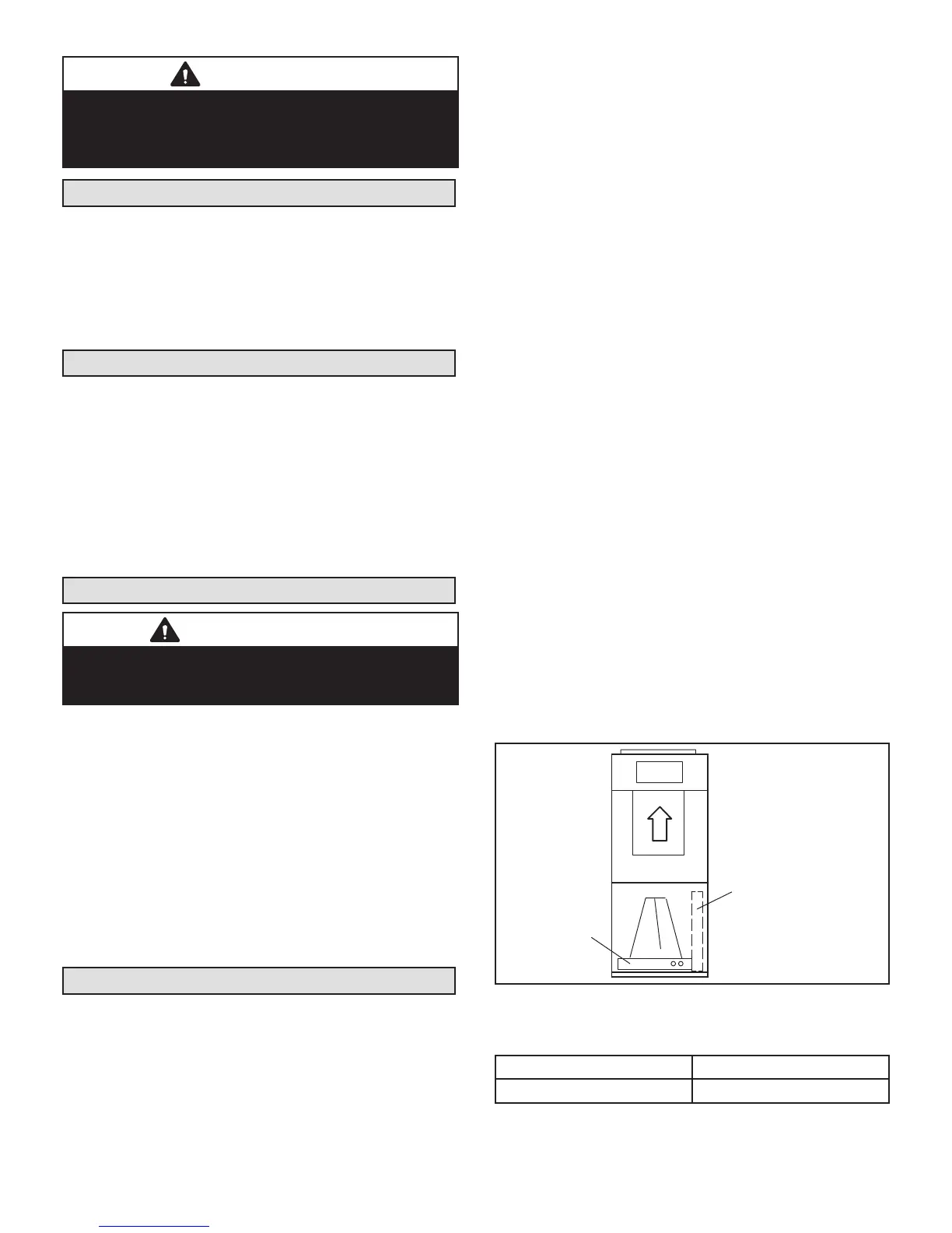
4 - After removing the horizontal drain pan, place the
unit in the desired location. Set unit so that it is level.
Connect return and supply air plenums as required
using sheet metal screws as illustrated in gure 1.
5 - Install units that have no return air plenum on a
stand that is at least 14" from the oor to allow for
proper air return. Lennox offers an optional upow
unit stand as listed in table 1.
HORIZONTAL DRAIN PAN
(MUST BE REMOVED)
UP-FLOW /
DOWN-FLOW
DRAIN PAN
FIGURE 1. Upow Conguration
TABLE 1. Optional Side-Return Unit Stand
(Upow Only)
Model Kit Number
All unit sizes 45K32
 Loading...