Page 6
Use the following procedures to congure the unit for hor-
izontal left-hand discharge operations:
1 - Before operating the unit, remove access panels
and the horizontal drip shield (-060 model) and the
corrugated padding between the blower and coil
assembly. Discard the corrugated padding.
2 - Pull the coil assembly from unit. Pull off the
horizontal drain pan.
3 - Remove the drain plugs from back drain holes on
horizontal drain pan and reinstall them on front
holes.
IMPORTANT
After removal of drain pan plug(s), check drain hole(s)
to verify that drain opening is fully open and free of any
debris. Also check to make sure that no debris has fallen
into the drain pan during installation that may plug up the
drain opening.
4 - Rotate drain pan 180º front-to-back and install it on
the opposite side of the coil.
5 - Remove screws from top cap. Remove horizontal
drip shield screw located in the center of the back
coil end seal as illustrated in gure 4 on page 5.
6 - Rotate horizontal drip shield 180º front-to-back.
7 - Remove plastic plug from left hole on coil front
end seal and reinstall plug in back hole. Reinstall
horizontal drip shield screw in front coil end seal.
Drip shield should drain downward into horizontal
drain pan inside coil.
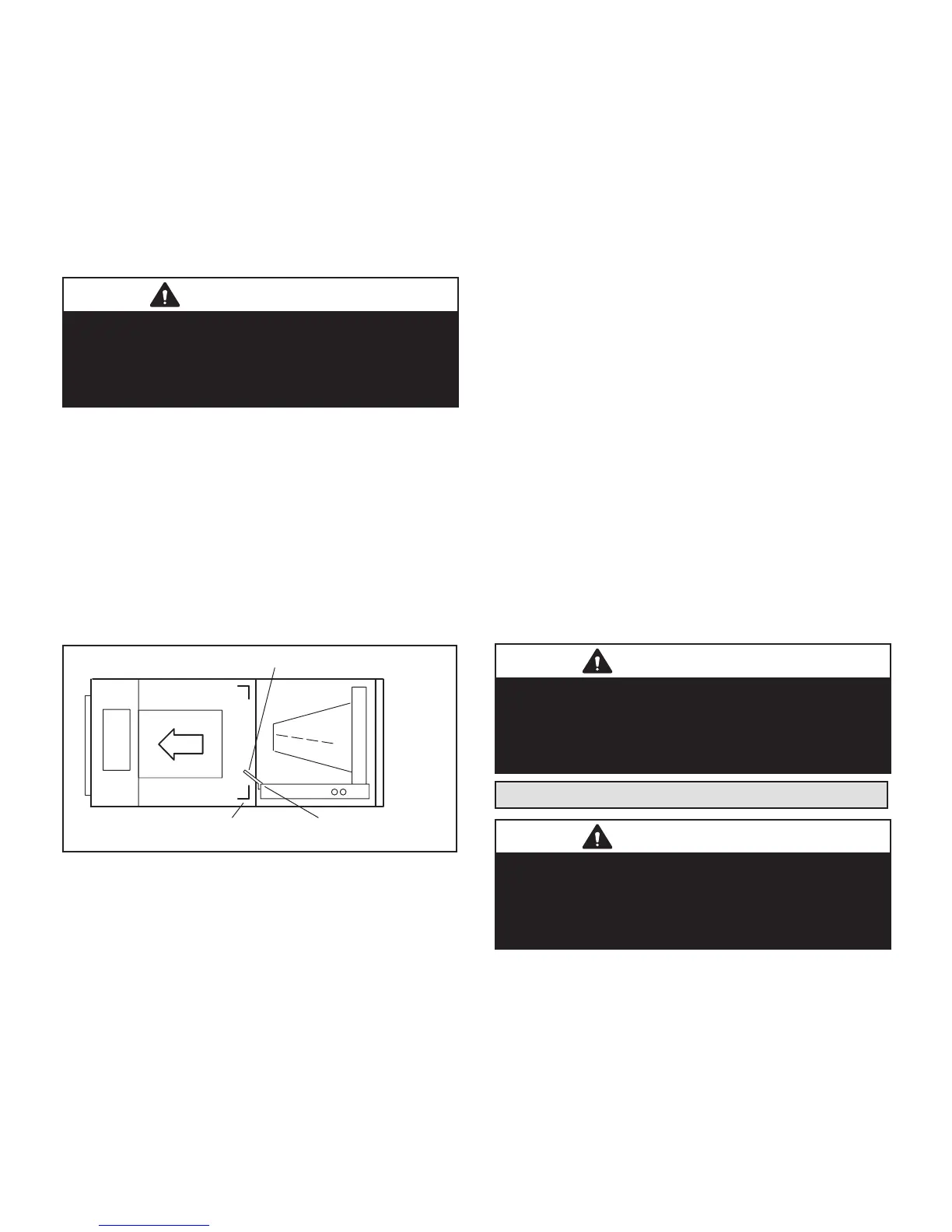
HORIZONTAL DRIP SHIELD (-060 MODEL)
DOWN-FLOW RAIL FRONT EDGE OF HORIZONTAL
FIGURE 5. Left-Hand Discharge Conguration
8 - Rotate top cap 180º front-to-back and align with
unused screw holes. Holes must align with front and
back coil end plates. The top cap has a 45º bend on
one side and a 90º bend on the other. The 90º bend
must be on the same side as the horizontal drain
pan as illustrated in gure 4 on page 5.
NOTE – Be very careful when reinstalling the screws into
the coil end plate engaging holes. Misaligned screws may
damage the coil.
9 - From the upow position, ip cabinet 90º to the
left and set into place. Replace blower assembly.
Secure coil in place by bending down the tab on the
cabinet support rail as illustrated in gures 4 and 5.
10 - Install the horizontal shield (-060 model) on the
front edge of the horizontal drain pan as illustrated
in gure 5 on page 6.
NOTE – For horizontal applications in high humidity ar-
eas, remove the downow rail closest to the drain pan. To
remove rail, remove screw from rail at back of unit and at
cabinet support rail. Remove downow rail then replace
screws. Also, seal around the exiting drain pipe, liquid and
suction lines to prevent inltration of humid air.
11 - Knock out drain seal plate from access door. Secure
plate to cabinet front ange with screw provided.
12 - Flip access door and replace it on the unit.
13 - Set unit so that it is sloped 1/4ʺ toward the drain
pan end of the unit. Connect return and supply air
plenums as required using sheet metal screws.
14 - If suspending the unit, it must be supported along the
entire length of the cabinet. If using chain or strap,
use a piece of angle iron or sheet metal attached
to the unit (either above or below) so that the full
length of the cabinet is supported. Use securing
screws no longer than 1/2ʺ to avoid damage to coil
or lter, as illustrated in gure 3 on page 5. Connect
return and supply air plenums as required using
sheet metal screws.
DOWNFLOW APPLICATION
NOTE – If downow application is required, separately
order kit number 83M57 and install per kit’s instructions.
Also use metal or class I supply and return air plenums.
Use the installation instruction provided with the downow
kit.
IMPORTANT
If electric heat section with circuit breakers (ECB29) is
installed in a CBA27UHE unit in a downow application,
the circuit breakers must be rotated 180° to the UP
position. See ECB29 installation instructions for more
details.
Brazing Connections
IMPORTANT
To prevent the build-up of high levels of nitrogen when
purging, it must be done in a well-ventilated area. Purge
low-pressure nitrogen (1 to 2 psig) through the refrigerant
piping during brazing. This will help to prevent oxidation
and the introduction of moisture into the system.
All coils are equipped with a factory-installed, internally
mounted check/expansion valve.
The air handler’s coil line sizes are listed in table 2. Use
Lennox L15 (sweat) series line sets (refer to the outdoor
unit Product Specications (EHB) for proper size, type
and application). For eld-fabricated refrigerant lines, see
the piping section of the Lennox Unit Information Service
Manual.
 Loading...