Page 8
Inspecting and Replacing Filters
IMPORTANT
Filter access panel must be in place during unit operation.
Excessive warm air entering the unit may result in water
blow-off problems.
Filters may be duct-mounted or installed in the cabinet. A
lter is installed at the factory. Note that lter access door
ts over access panel. Air will leak if the access panel is
placed over the lter door.
Filters should be inspected monthly and must be cleaned
or replaced when dirty to assure proper air handler oper-
ation.
Reusable lters supplied with some units can be washed
with water and mild detergent. Some units are equipped
with standard throw-away type lters which should be re-
placed when dirty.
To replace lter:
1 - Loosen the thumbscrews holding the lter panel in
place. Remove the dirty lter.
2 - Insert new lter and replace panel.
TABLE 3. Filter Dimensions
CBA27UHE Filter Size – In. (mm)
-018, -024, -030, -036 20" x 20" (508mm x 508mm)
-042, -048, -060 20" x 24" (508mm x 610mm)
Sealing the Unit
WARNING
There must be an airtight seal between the bottom of
the air handler and the return air plenum. Use berglass
sealing strips, caulking, or equivalent sealing method
between the plenum and the air handler cabinet to
ensure a tight seal. Return air must not be drawn from a
room where this air handler or any gas-fueled appliance
(i.e., water heater), or carbon monoxide-producing
device (i.e., wood replace) is installed.
Seal the unit so that warm air is not allowed into the cabi-
net. Warm air introduces moisture, which results in water
blow-off problems. This is especially important when the
unit is installed in an unconditioned area.
ABOVE
FINISHED
SPACE?
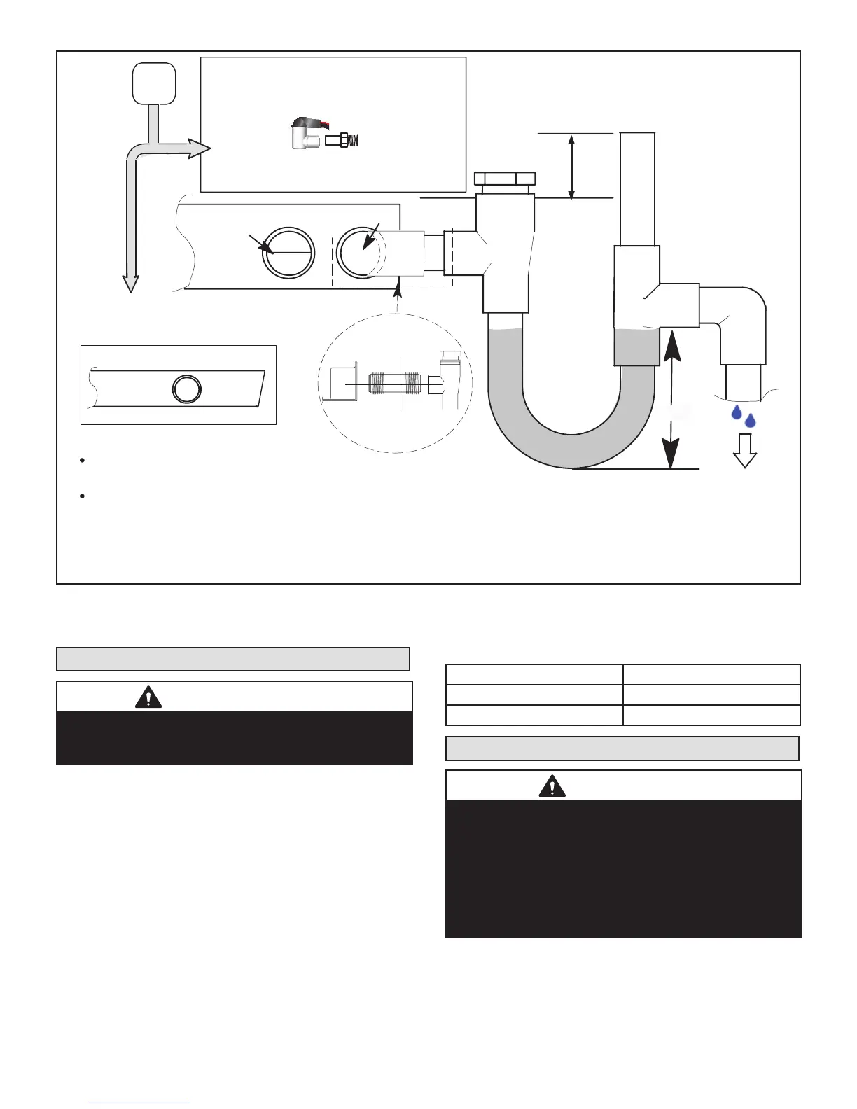
OVERFLOW DRAIN LINE
ALWAYS RUN AN OVERFLOW DRAIN LINE. IF NOT POSSIBLE TO
ROUTE OVERFLOW DRAIN LINE, INSTALL LOW VOLTAGE
OVERFLOW SWITCH KIT. WIRE KIT TO SHUT DOWN
COMPRESSOR PER INSTRUCTIONS.
NO
YES
LENNOX #
X3169
CLEAN OUT
VENT
PRESS IN
(DO NOT GLUE)
VENT MUST EXTEND
ABOVE HEIGHT OF
COIL DRAIN PAN BY
TWO INCHES (51MM)
1” X 3/4” X 3/4”
REDUCING
TEE WITH
PLUG
LENNOX
1
P-TRAP
49P66, J-TRAP #
91P90 OR ANY
PVC SCH 40 P- OR
J-TRAP 3/4”
OVERFLOW
DRAIN
AIR HANDLER DRAIN PAN
WHEN A COIL IS LOCATED ABOVE A FINISHED SPACE, A
3/4” (19.1MM) SECONDARY DRAIN LINE MUST BE:
CONNECTED TO SECONDARY DRAIN PAN
OR
CONNECTED TO THE OVERFLOW DRAIN OUTLET OF
THE AIR HANDLER DRAIN PAN.
TRAPS MUST BE DEEP ENOUGH TO OFFSET MAXIMUM STATIC DIFFERENCES —
GENERALLY, TWO INCHES (51MM).
DRAIN LINE SHOULD
SLOPE A MINIMUM OF
ONE INCH PER 10
FEET (25MM PER 3
METERS)
NOTE — WHEN A AIR HANDLER IS LOCATED
ABOVE A FINISHED SPACE THE SECONDARY
DRAIN PAN MUST HAVE A LARGER FOOTPRINT
THAN THE AIR HANDLER.
MAIN
DRAIN
TO APPROVED
DRAIN
FOR NEGATIVE PRESSURE COILS (BLOWER
AFTER COIL) TRAPS ARE REQUIRED ON ALL
DRAIN LINES CONNECTED TO COIL.
COMPACT OVERFLOW SWITCH WITH 3/4” FEMALE SLIP INLET
AND MALE ADAPTER, TWO PART DESIGN FOR USE WHERE
OBSTRUCTIONS PREVENT DIRECT THREADING
SECONDARY
DRAIN PAN
2”
(51MM)
TRAP DEPTH
1
LENNOX P-TRAP 49P66 REQUIRES A LARGER INSTALLATION SPACE THAN THE J-TRAP 91P90.
2
PIPE NIPPLE PROVIDED IN BAG ASSEMBLY - SCH 80, 3/4” I. D. X 5” - 34K7401 (1): CUT THE PIPE IN HALF AND USE IT TO ROUTE THE MA IN DRAIN.
MAIN
DRAIN
PROVIDED
PIPE NIPPLE
2
CUT TO
REQUIRED
LENGTH
SIDE VIEW
FIGURE 8. Typical Main and Overow Drain
 Loading...