Page 18
15-Blower Motor Overload Relay S42
(5 & 10 HP Motors only)
Units equipped with 5 and 10 horsepower indoor blower
motors are also equipped with a thermal overload relay
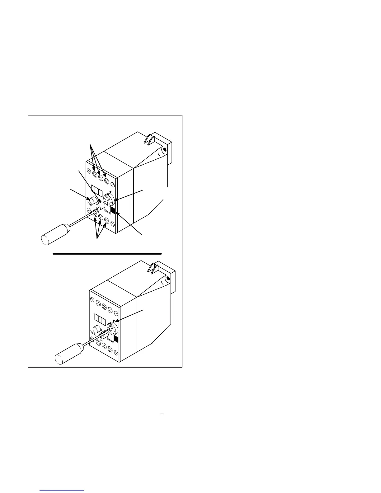
connected inline with the blower motor. See figure 11. The
relay monitors the current flowing to the blower motor.
When the relay senses an overload condition, a set of N.C.
contacts in the relay open to deenergize all control volt
age in the unit.
FIGURE 11
OVERLOAD RELAY S42
MANUAL/AUTO RESET ADJUSTMENT
DIAL ADJUSTMENT
TRIP INDICATION
WINDOW
TRIP RANGE
ADJUSTMENT
TEST BUTTON
PUSH TO
TEST
MANUAL/AUTO
RESET SWITCH
H=MANUAL RESET
A=AUTO RESET
LINE VOLTAGE IN
SWITCHED VOLTAGE OUT
FIND FULLLOAD AMPS (FLA)
OF INDOOR BLOWER MO
TOR MARKED ON UNIT
RATING PLATE. SET
DIAL TO THIS
VALUE. RELAY
WILL THEN AU
TOMATICALLY
TRIP WHEN FLA
EXCEEDS 125%
OF SET VALUE.
ADJUST
TO
POINTER
16-Compressor Delay DL15
(1603 Y voltage, all 1853 voltages only)
Time delay DL15 is a SPST N.O. timedelay switch.
Once energized, the delay waits 30 seconds + 3 sec
onds before closing. The purpose of the delay is to pre
vent voltage drop at the contactor coil due to (the possi
bility of) multiple contactors being energized at the
same time. With the delay added, only two contactors
(K1 and K10) can energize at the same time while the
third contactor (K2) must wait 30 seconds before ener
gizing. When thermostat demand stops, DL15 immedi
ately opens and resets.
In both units, the delay is wired in series with compres
sor contactor coil (K2). In CHA161603 units, the delay
is energized upon receiving a call for second stage
cooling. In CHA161853 units the delay is energized si
multaneously with compressor 1 contactor K1 and con
denser outdoor fan contactor K10.
In CHA161853 units, once contactor K2 is energized,
a set of N.O. K2-2 auxiliary contacts close to bypass the
time delay (wired in parallel with time delay DL15).
When K2-2 closes, the resulting shunt eliminates any
load added by the time delay (allows K2 to receive full
voltage).
17-Pilot Relay Board A11
(1853, 2553, 2753, 3003 only)
A11 is a pilot relay board (figure 12) used in all CHA16
15 ton and larger units. Pilot relays are used in 24VAC
control circuits to limit voltage drop caused by a long
run of thermostat wire. The relays on the circuit board
are added electrically in between the thermostat (or
thermostat control system) and the contactors in the
unit.
Relays draw much less current from the transformer
than the unit contactors. When a long run of thermostat
wire is used from the unit to the thermostat and back to
energize unit contactors, current drawn by the contac
tors could potentially cause voltage drop resulting in
contactor chattering. The pilot relays are added be
tween the thermostat and the contactors (refer to unit
wiring diagram) to electrically isolate the contactor
coils from the thermostat wire and thereby minimize the
potential for voltage drop at the contactors.
18-Indoor Blower Contactor K3 (all units)
K3 is a 24V to line voltage contactor used to energize the
indoor blower motor in response to blower demand. In cool
ing mode K3 is energized by pilot relay K46 in response to
cooling or constant fan demand. In heating mode K3 is en
ergized by relays K20 or K25 (in the heating section) in re
sponse to heating demand. All units use threepoledouble
break contactors.

 Loading...
