Page 12
506101−01 07/09
REQUIRED EQUIPMENT
Equipment required to flush the existing line set and indoor
unit coil:
S Two clean HCFC−22 recovery bottles,
S Oilless recovery machine with pump-down feature,
S Two gauge sets (one for HCFC−22; one for
HFC−410A).
PROCEDURE
1. Connect the following:
S HCFC−22 cylinder with clean refrigerant to the
suction service valve,
S HCFC−22 gauge set to the liquid line valve,
S Recovery machine with an empty recovery tank to
the gauge set.
2. Set the recovery machine for liquid recovery and start
the recovery machine. Open the gauge set valves to
allow the recovery machine to pull a vacuum on the
existing system line set and indoor unit coil.
3. Invert the cylinder of clean HCFC−22 and open its
valve to allow liquid refrigerant to flow into the system
through the suction line valve. Allow the refrigerant to
pass from the cylinder and through the line set and the
indoor unit coil before it enters the recovery machine.
4. After all of the liquid refrigerant has been recovered,
switch the recovery machine to suction recovery so
that all of the HCFC−22 suction is recovered. Allow the
recovery machine to pull a vacuum on the system.
5. Close the valve on the inverted HCFC−22 drum and
the gauge set valves. Pump the remaining refrigerant
out of the recovery machine and turn the machine off.
6. Use dry nitrogen to break the vacuum on the
refrigerant lines and indoor unit coil before removing
the recovery machine, gauges and refrigerant drum.
Installing New Indoor Unit Metering
Device
XC16 units can be configured for use in with HFC−410A
fixed orifice or TXV metering devices. This section
provides instructions on installing either a fixed orifice or
TXV refrigerant metering device.
1
2
3
4
5
6
7
8
9
10
11
12
1/8 TURN
1
2
3
4
5
6
7
8
9
10
11
12
1/2 TURN
Figure 22. Tightening Distance
XC16 ENGINEERING HANDBOOK
See the XC16 Engineering Handbook for approved
indoor/outdoor match−ups, applicable TXV kit and
application information. The following is the typical
contents of a TXV kit:
TXV (1)
COPPER
MOUNTING
STRAP (1)
HEX HEAD BOLTS
AND NUTS (2)
TEFLON
RINGS (2)
Figure 23. TXV Kit Components
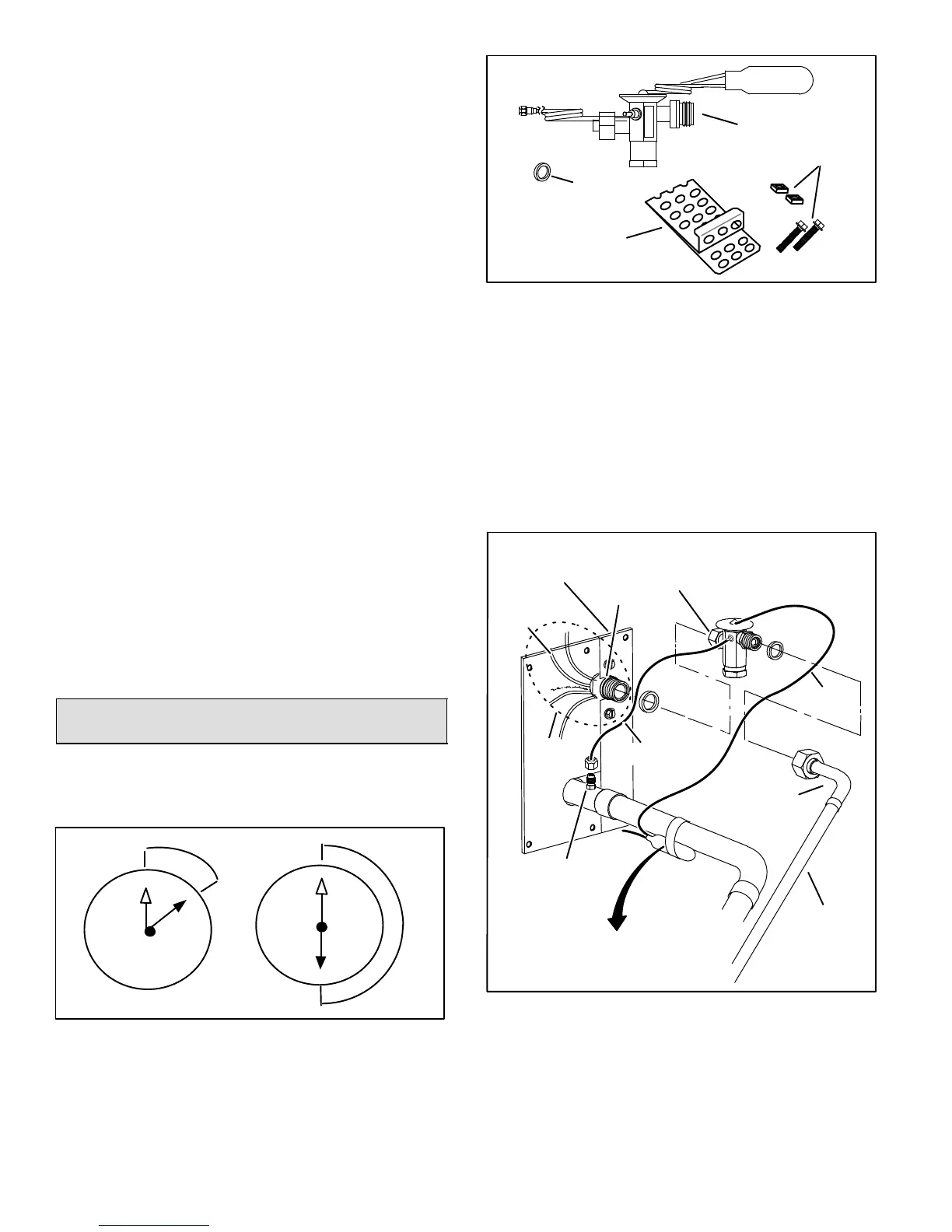
TYPICAL TXV INSTALLATION PROCEDURE
The TXV unit can be installed internal or external to the
indoor coil. In applications where an uncased coil is being
installed in a field−provided plenum, install the TXV in a
manner that will provide access for field servicing of the
TXV. Refer to Figure 24 for reference during installation of
TXV unit.
To prevent any possibility of water damage, properly
insulate all parts of the TXV assembly that may sweat due
to temperature differences between the valve and its
surrounding ambient temperatures.
TWO PIECE
PATCH PLATE
(UNCASED COIL
ONLY)
SUCTION
LINE
LIQUID LINE
ORIFICE
HOUSING
DISTRIBUTOR
TUBES
LIQUID
LINE
MALE EQUALIZER LINE
FITTING (SEE FIGURE 26
FOR FURTHER DETAILS)
SENSING
LINE
EQUALIZER
LINE
TXV
TEFLON
RING
(Uncased Coil Shown)
SENSING BULB INSULATION IS
REQUIRED IF MOUNTED EXTERNAL
TO THE COIL CASING. SEE FIGURE 25
FOR BULB POSITIONING.
STUB END
TEFLON
RING
LIQUID LINE ASSEMBLY
WITH BRASS NUT
DISTRIBUTOR
ASSEMBLY
Figure 24. Typical TXV Installation
1. Remove the field−provided fitting that temporary
reconnected the liquid line to the indoor unit’s
distributor assembly.
2. Install one of the provided Teflon rings around the
stubbed end of the TXV and lightly lubricate the
connector threads and expose surface of the Teflon
ring with refrigerant oil.

 Loading...