Page 2
506101−01 07/09
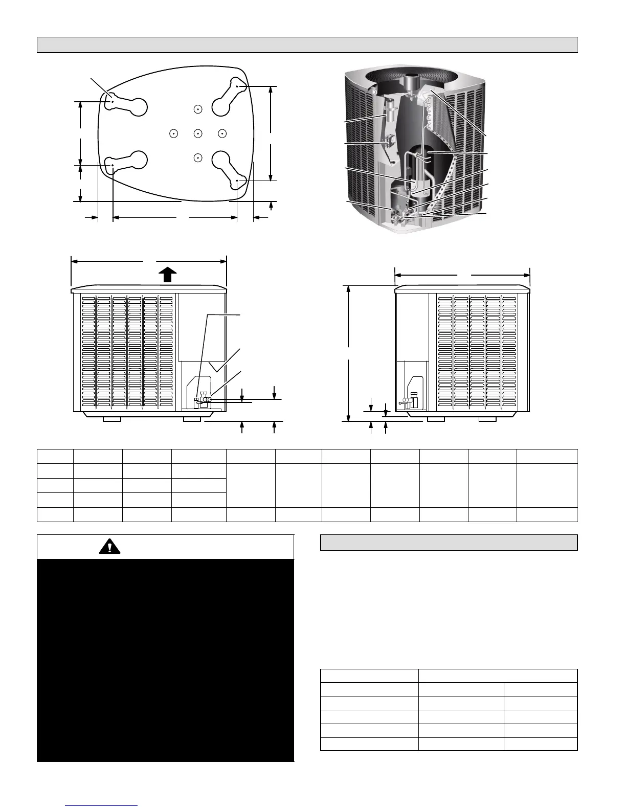
Unit Dimensions − Inches (mm)
ELECTRICAL
INLETS
SIDE VIEW
DISCHARGE AIR
SUCTION LINE
CONNECTION
LIQUID LINE
CONNECTION
4−1/4(1
08)
4−3/4
(121)
1 (25)
2 (51)
SIDE VIEW
C
B
A
D
G
K
J
E
F
UNIT SUPPORT
FEET
XC16 BASE WITH ELONGATED LEGS
H
OUTDOOR FAN
COMPRESSOR
HIGH PRESSURE SWITCH
LOW PRESSURE SWITCH
VAPOR LINE
VAPOR VALVE AND GAUGE
PORT/SUCTION LINE
CONNECTIONS
RUN
CAPACITOR
CONTACTOR
DISCHARGE
LINE
FILTER DRIER/
LIQUID LINE
CONNECTIONS
XC16 PARTS ARRANGEMENT
XC16 A B C D E F G H J K
−024
39 (991) 30−1/2 (775) 35 (889)
13−7/8 (352) 7−3/4 (197) 3−1/4 (83) 27−1/8 (689) 3−5/8 (92) 4−1/2 (114) 20−5/8 (524)−036
45 (1143) 30−1/2 (775) 35 (889)
−048
39 (991) 30−1/2 (775) 35 (889)
−060
39 (991) 35−1/2 (902) 39−3/8 (1001) 16−7/8 (429) 8−3/4 (222) 3−1/8 (79) 30−3/4 (781) 4−5/8 (117) 3−3/4 (95) 26−7/8 (683)
WARNING
This product and/or the indoor unit it is matched
with may contain fiberglass wool.
Disturbing the insulation during installation,
maintenance, or repair will expose you to fiberglass
wool dust. Breathing this may cause lung cancer.
(Fiberglass wool is known to the State of California
to cause cancer.)
Fiberglass wool may also cause respiratory, skin,
and eye irritation.
To reduce exposure to this substance or for further
information, consult material safety data sheets
available from address shown below, or contact
your supervisor.
Lennox Industries Inc.
P.O. Box 799900
Dallas, TX 75379−9900
General Information
These instructions are intended as a general guide and do
not supersede local codes in any way. Consult authorities
who have jurisdiction before installation.
When servicing or repairing HVAC components, ensure
caps and fasteners are appropriately tightened. Table 1
lists torque values for typical service and repair items.
Table 1. Torque Requirements
Part Recommended Torque
Service valve cap 8 ft.− lb. 11 NM
Sheet metal screws 16 in.− lb. 2 NM
Machine screws #10 28 in.− lb. 3 NM
Compressor bolts 90 in.− lb. 10 NM
Gauge port seal cap 8 ft.− lb. 11 NM

 Loading...